Solarpunk Futures
Solarpunk Futures invites participants to build something they wish to see in a future city that is just and sustainable. It consists of a microgrid that distributes low voltage (5 volts) electricity from a solar panel or handcrank generator throughout the network to power creations made by participants, which use slow motors and LED lights. It's designed to be modular, a little like a train set, so you can build as much or as little as you need, and configure it in whatever shape you wish to. It can be run as a drop-in activity in an informal environment, where curious people passing by can join in and contribute in waves, and can also work as a workshop for up to 12 people participating at a time.
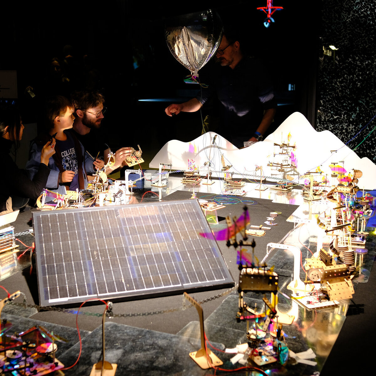
The goal of Solarpunk Futures is to create a space for people of all ages to imagine, build, and reflect together about the sustainable future they wish to see. As a creative learning activity it is designed to invite open-ended exploratory creativity, so there is no single "solution" or correct answer to the prompt "Build what you wish to see in a sustainable future." While it is designed to support learning and imagination for the participants, it can also function as a public artwork that invites the audience to reflect on their own dreams for a sustainable future, as well as their fellow citizens.
The activity begins with an invitation to reflect on the builds made by those who came before. Next the contributor is invited to build their own creation, after which we record a brief video of it while only their voice is recorded as they respond to the prompt: "Tell us what you made, and what you wish to see in the future."
Currently, we are exploring ways to use local only open-source AI models (that do not upload or share data with the cloud) to catalog, summarize, and re-present these build recordings for the next participants, and to analyze the data from each run of the activity. Our goal is to use the activity as a tool for democratic advocacy around sustainable futures. If you are interested in building your own solarpunk future set, you'll find everything you need here. If you would like someone to setup and run a solarpunk futures experience, contact Amos at amos (the little swirly at thing) amosamos.net.
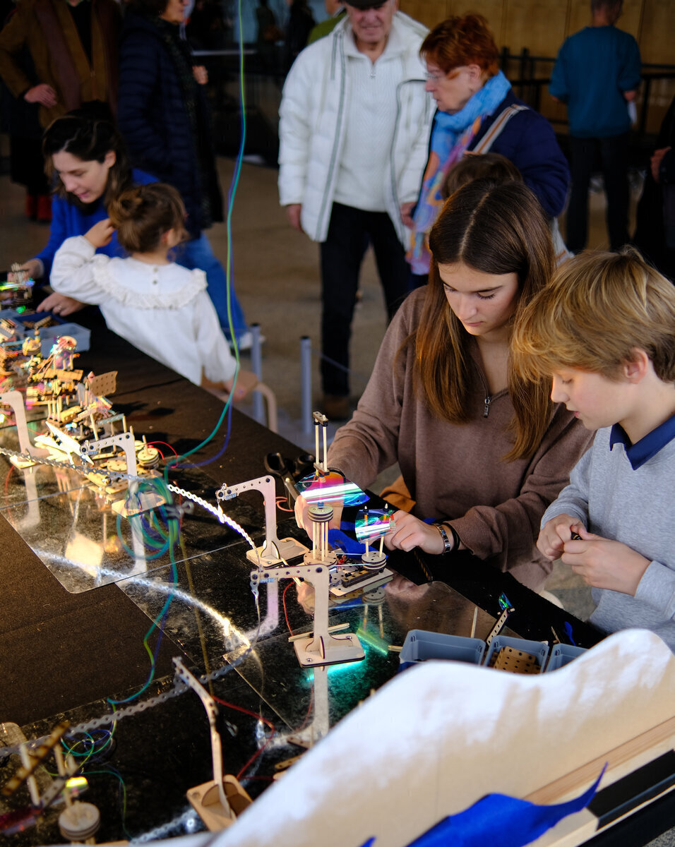
Solarpunk Futures was developed by Amos Blanton as part of research with the Experimenting, Experiencing, Reflecting Project. The creative producer for "Your Solarpunk Future" at the 2025 Festival of Future Nows in the Neue Nationale Gallery in Berlin, the event shown here in images and video, was Andrew Amondson, who also contributed to the design.
Facilitating Solarpunk Futures
Location and Setup
Solarpunk futures can be run as a drop in activity wherever there are people who will be curious enough to try it, or as a traditional "start to finish" sign up workshop. A 2x3 table can support approx. 12 simultaneous builders, working together in pairs. Often these are parents and their children, ages 6 and up because the materials can be somewhat "fiddly" for little hands.
As with all creative learning activities, it's important that the facilitators have had time to try the activity themselves, in order to get familiar with the elements and the process of building, as well as how to do basic debugging.
The ideal setup has the table with the city in a high traffic area where people are likely to have spare to time to spend, such as in the lobby of a library, an art gallery, science museum, or similar public space. To provide power for the city, South facing window access (North facing in the Southern hemisphere) is a plus, as that allows for placement of the solar panel in the sun. Without access to natural light, a tungsten or halogen light can be used. For the event at the Neue National Gallery, we used a 750 watt halogen stage light pointed at a 50 watt 12 volt panel with a 5 Volt voltage regulator attached. But as little as 100 watts of halogen or tungsten light into a small USB panel will likely suffice.
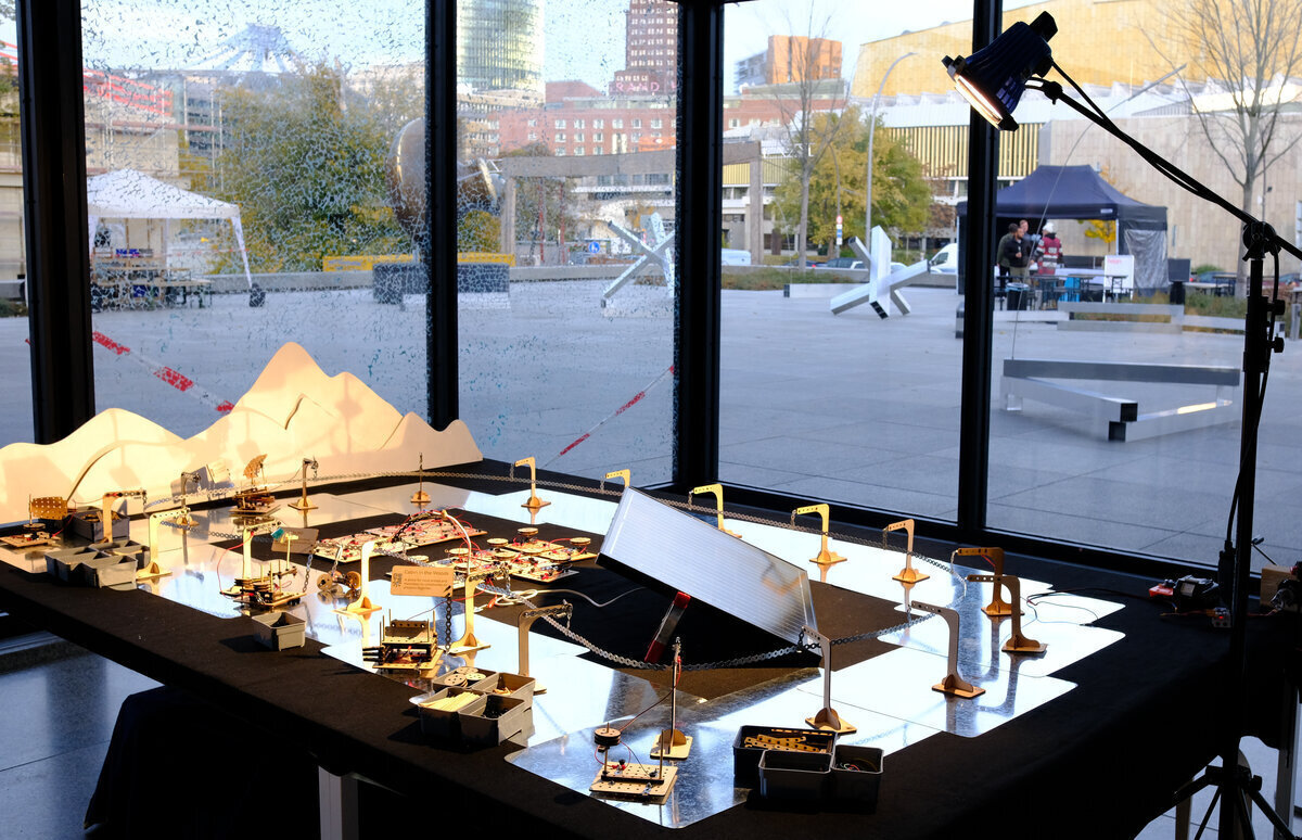
Initial setup involves laying down the felt before placing each of the steel plates in a pattern - circular or otherwise - that allows them to overlap, as they need to be touching for the electricity to be able to make a complete circuit. Place a single pylon in the middle of each steel plate - favoring "Short-detecting" pylons wherever you plan to have a space for people to build.
Next unreel and mount a loop of fixing strap so that it connects all of the pylons. Attach the positive lead from the 5V output of your solar panel to this loop via a basic pylon, and the negative lead to the steel plates.
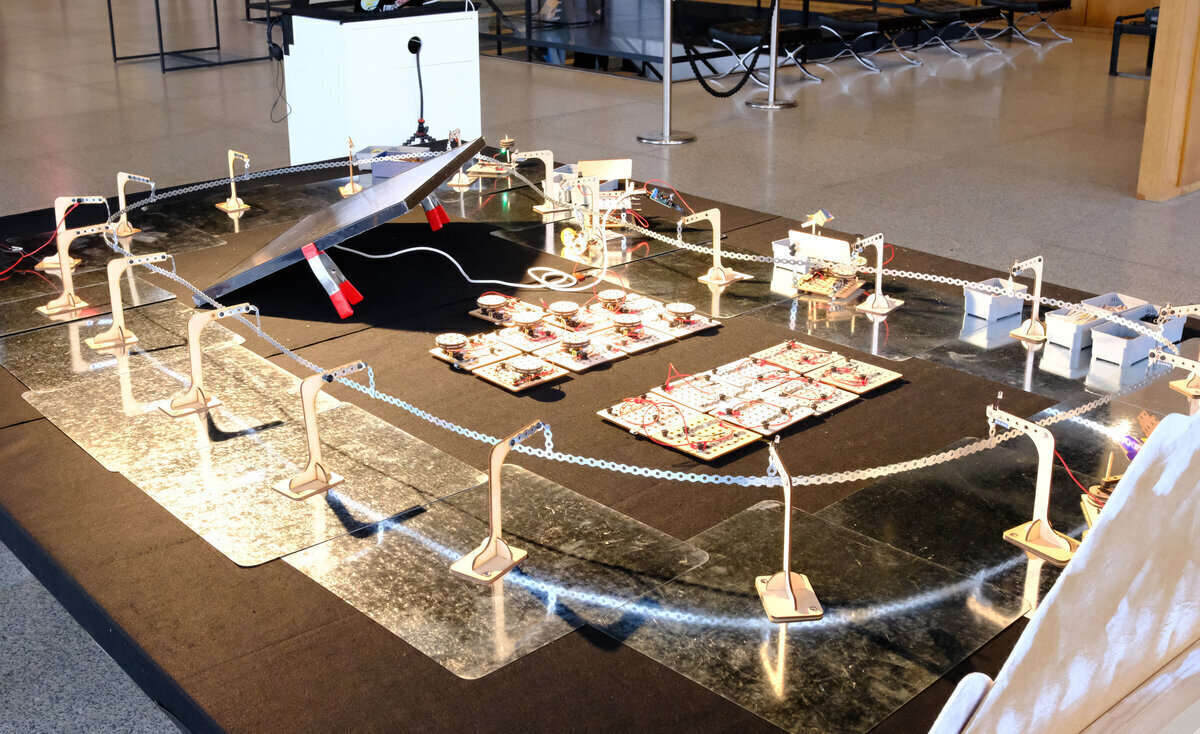
Next build 2-3 "sample projects" - builds that demonstrate 1) a very simple mechanism that is the least intimidating example you can imagine, demonstrating the low floor for participants who feel anxious when they encounter unfamiliar technologies. 2) A complex and technically interesting build that you or your colleagues spent time on, that demonstrates the potential for deeper exploration (high ceiling.) 3) Something completely different. Have these on the grid and operating for potential participants to observe.
Next, prepare all the build plates. We find that for drop in activities, it's best to keep the focus on the build, rather than learning about circuits / etc. So before the workshop, we attach one motor and one LED light to each build plate, so that all new participants have a functioning starting point to build from.
Finally, lay out the materials and a build plate, connected to a pylon, in each area where you plan to seat participants. For drop in activities, 2 build areas (for 2-3 people each) is manageable for 1-2 faciliators, as you will be spending some of your time introducing the project to passersby, managing the queue or sign up list, taking apart old builds to free up plates and elements for new ones, etc.
Running the Activity
Facilitation of creative learning activities involves supporting learners in getting comfortable with the materials so they can explore possibilities and build whatever emerges from their imagination. Facilitation is a skill that's complex enough that it can be developed and refined over an entire lifetime. For a brief introduction in the form of a one pager, see the Tinkering Studio at the Exploratorium's Facilitation Field Guide, or consider taking one of their online courses.
Facilitators should welcome new contributors and explain the nature and goals of the activity. Invite them to sit down in the build area or join a queue. While they are waiting, invite them to observe what others have made, and reflect on what they want to see in a sustainable future.
When seated, introduce the build plate and connect it to the pylon to show how it works. In case they wish to stop the motor while they build, show them how to put a piece of paper between the magnet on the build plate and the steel ground plate, which will break the circuit and stop the motor and LED. Introduce the elements and let them know they are welcome to ask for assistance any time. Be aware that many people feel anxious about technology, as though they should somehow already know how everything works. Try to use a reassuring tone to help them feel comfortable just playing with materails and ideas.
Ideally the builders will all be building on build plates connected to "short detecting pylons", which have red LED lights that turn on whenever there is a short circuit behind the pylon. A short circuit will be rare, but when it happens it is usually caused some piece of metal that's allowing power to go directly from the positive power loop to the ground plane of the steel plates (so the circuit is "short" because it is skipping past the places where we want the electricity to go - which is through the LED and motor.) A short circuit may slow or stop all builds on the table by taking their power away. If you see a short indicator LED light up on a pylon, or everything stops working, patiently look for something metal that is connecting the positive and negative sides of the build plate, or the power loop to the build plate. Once you remove the short circuit, the pylon light should turn off and everything should start working again.
When a contributor is finished, make a brief video with the camera pointed at the working build as they answer the question "Tell us what you made, and what you wish to see in the future." After the recording is done, ask them where in the city they would like to place their build, and move it to that location, re-connecting it to the nearest pylon.
Once all the build plates have been used, you'll need to choose one or two at a time to take apart and prepare for the next participants. You can do this according to whatever criteria you choose: from how long they've been out to how inspirational and interesting you find the designs. Don't worry - all builds are documented, and old has to make way for new in order for cities to evolve.
Building Solarpunk Futures
Solarpunk futures is open source and designed to be build with a lasercutter and other tools commonly found in most makerspaces.
The main components you need to source and build are:
- Pylons - These hold up the plumber's strap power rail and distribute 5V positive power to connected buildings. They have magnetized bases so they hold onto the steel plates, which act as the negative or "ground" to complete the circuit.
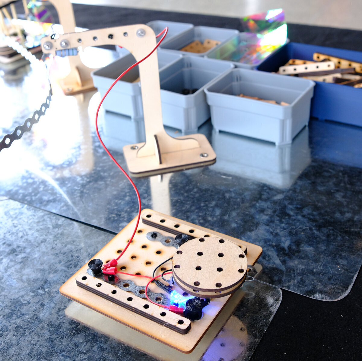
- Build plates - These are what participants build onto. To supply power to components attached to them, their positive rail is wired to a pylon. Their negative rail is connected to a magnetized "foot" that contacts the steel plates and completes the circuit. This allows the motors or LEDs connected to these power rails to work.
- Construction elements - These are beams, dowels, LEDs, motors and pulleys that participants use to build their creations.
All digital files can be found in the Solarpunk Futures folder in the project's Gitlab repository.
Sourcing Parts
You can find a Bill of Materials with links and approx. costs as of Jan. 2026. - Quantities in this BOM are for 20 steel plates, pylons, and build plates, which is enough for a 2x3 meter table. You can make it larger or smaller, according to your wishes. - For the galvanized steel plates, it is possible to contact the aliexpress vendor and ask them for a quote for the same sized square plates but with rounded corners (r30), which look nicer. When I did that the price they offered was the same as the price for the 40x40 cm squares with sharp corners. If you get normal square plates, be prepared to file the corners down as they may be sharp. - The snap rivets are used to hold the ring connectors in place between the pylons and the build plates, and for motors and lights to the power rails. These can usually be found online through Mouser or Digikey. I'm seeking a simpler to source, less expensive option that is still easy to insert and remove, so let me know if you find one. - All lasercut items are made from 3mm plywood with the exception of the building beams, which are 6mm.
Tools
- Metals shears for cutting the 12mm metal fixing strap
- Pliers
- Electrical connector crimping tool
- Wire strippers
- Soldering station
- Hot glue gun
Building Pylons
The Pylons hold up the plumber strap that distributes the power, and provide power to the build plates. You can build regular pylons, which are simple. But at least for areas where participants are actively building, we recommend short-detecting pylons. These have an integrated LED that lights when there is a short circuit between the pylon and ground (usualy caused by a metal object connecting the positive side of the build plate to ground.) When people are building, it's best if they are connected to a short detecting pylon, so that the LED will indicate when there is a short circuit. Once they are done, you can move the build to a normal pylon somewhere else on the network, so that the build area is free for the next participant.
Note that short circuits will generally stop or drastically slow down everything on the network - which is fine. But you will want to remove the short to get things running again. The short circuit pylons make short circuits easier to find by indicating which pylon has one.
-
Begin by lasercutting 1 pylon in 3mm plywood with the pylon svg file. Because tolerances may vary between laser cutters, it's best to start with one cut which you build out from start to finish. If things are too tight or too loose, you can adjust things like hole diameter before cutting the rest.
-
The base of the pylon has two holes for magnets - put them in so the flat side is down, where it should touch the steel plate and hold onto it. If you are lucky, they should press fit in place with a little effort and stay put. If they are too hard to get in place, you can use a vice, file the edges of the hole a bit, or adjust the hole size in the digital file and lasercut another. If they can come out again once they are in place, you'll want to glue them in with CA glue, hot glue, or anything else suitable.
-
Assemble the pylon so it stands. It should press fit, but depending on how your lasercutter is calibrated, you may need to adjust the sizing or use glue. Press fit is nicer if you have to travel, as it enables you to break the pylons down again so they can be flat packed.
Short Detecting Pylons
-
Cut two lengths of strap, one 6 holes long for the top and one that is 5 holes long for the hook that holds the power loop.
-
Use two pairs of pliers to fold one end of the 5 hole length piece between the last two holes, so it forms a slot to hold the power rail. This is the bottom. Now grip it with one set of pliers around the top hole, and anothe set above the fold of the hook, and twist it 90 degrees.
-
Use the small machines screws to mount the 6 hole long piece along the top length of the pylon, but don't tighten them. Do the same with the mount for the hook at the top.
-
Resistors don't care about polarity, so orientation doesn't matter. Bend one leg of the resistor to form a hook over the machine screw that holds the hook, and place it between the hook and the wood of the pylon so they make contact. Bend the other leg of the resistor parallel to itself and then up so it can catch on the machine screw that holds front side of the 6 hole strap.
-
The LED makes the same connection, but it's important that the positive leg of the LED connects to the hook and the negative to the 6 hole length of strap. The positive leg is usually the one that is longer, but if you aren't sure, connect the LED to 5Volts of power to so you can be sure which leg is positive.
-
Cut and strip the wires for the LEDs, so that they can make good electrical contact with both pieces of strap. Wrap the corresponding wire part way around each screw.
-
Once all connections are in place, tighten the screws to hold everything in place.
-
To test a short detecting pylon, attach the hook to the powered network or another 5V source. Touch one end of a wire to the 6 hole strap behind the LED and the other to ground. The LED should light up when enough current can flow through the circuit. When connections are normal, there is more resistance, so there is normally not enough current to light the LED.
Regular Pylons
Regular pylons don't have a resistor or LED in parallel between the positive loop and the positive rail of the build plate. It's just a solid strip of strap going from the hook across the top of the pylon.
-
Cut a strip of plumber's strap 12 holes long.
-
Use two pairs of pliers to fold one end one hole in against itself, so it forms a hook or slot to hold the power rail.
-
Grip it 3 holes up from the bottom bend of the hook with one plier, and around the 5th hole with the other. Twist it 90 degrees so the hook is perpendicular to the pylon. Then bend the hook downward.
-
Make sure that the height of all pylon hooks are about the same, so that the power loop fits in the same place for all of them.
-
Use screws to attach the strap to the front and back holes of the pylon.
-
Regular pylons like this one are handy for connecting to the solar panel / power source, since you can pin the positive wire anywhere on the pylon
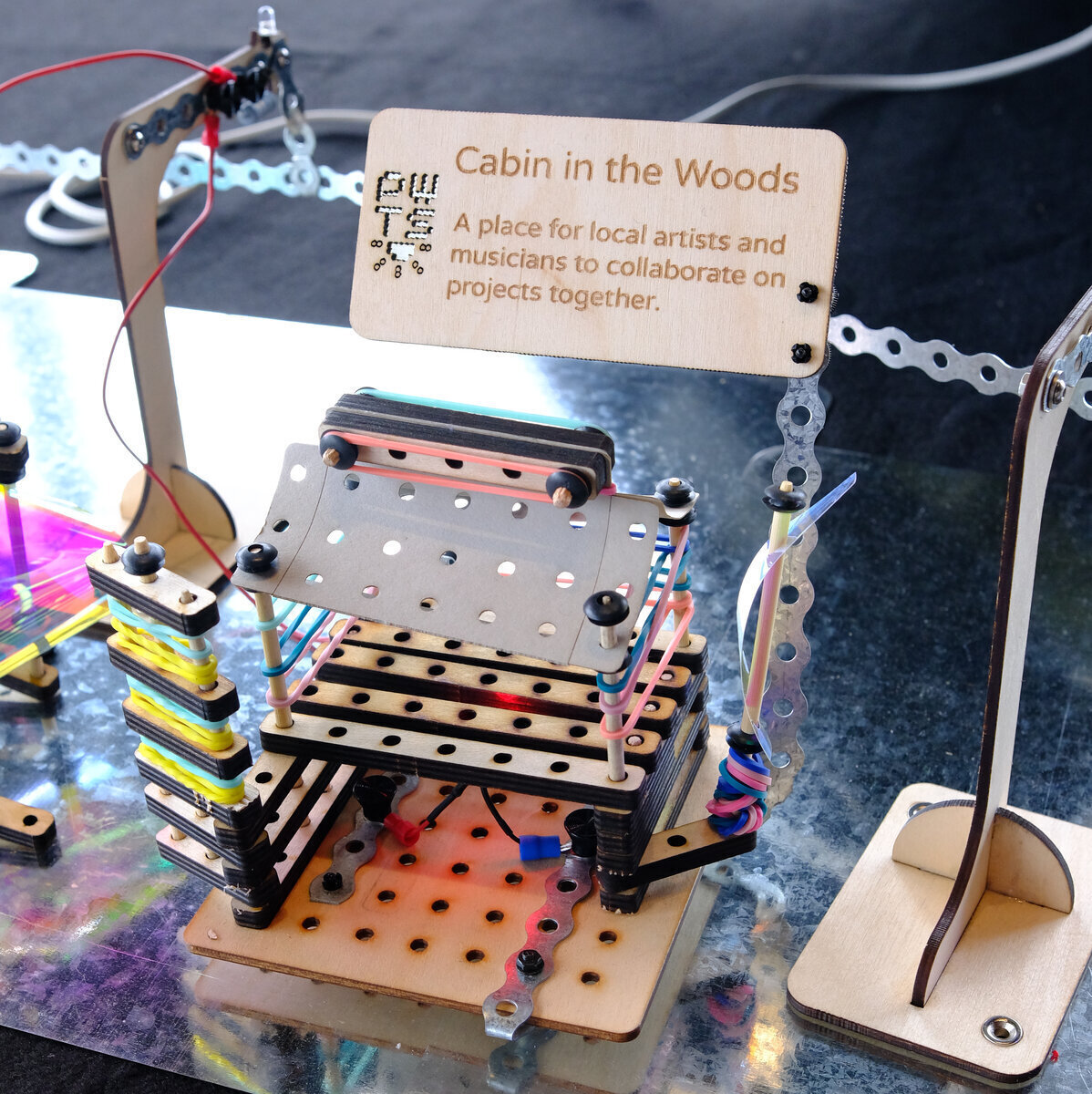
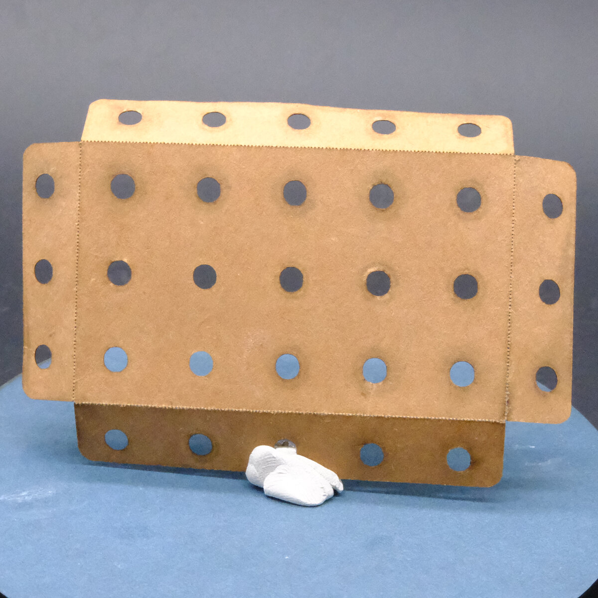
Building the Build Plates
A build plate serves as the base for the participant's creations, be it a building or a sculpture or something else entirely. They have two rails made of strap. The positive rail (the piece of strap that does not wrap around and contact to the steel ground plate) is connected to a pylon. The negative rail wraps around to the bottom of the plate and connects to a magnetic foot, which in turn connects to the steel ground plate. When a motor or LED is connected between the positive and negative power rails of the build plate, power flows from the power loop through the pylon across the components in the build plate, down to the steel ground plates, and back to the power source.
-
Begin by lasercutting one build plate from the build-plate.svg file. It's best to build the first plate completely and test it out to make sure that the tolerances for hole size and position are all correct, since these may vary by lasercutter.
-
Cut two lengths of strap: one for the postive rail that's 6 holes long, and the other for the negative, which is 10.
-
Place the positve rail so that the hole on one end is close to the edge of the build plate. Place a screw into a plastic spacer (with no washer) and put it through the plate and the positive rail from the bottom. Tighten is so much that the head of the screw goes up into the plastic spacer a millimeter or two. This is important - because if the screw makes contact with the metal groundplate, it will cause a short circuit.
-
Put a dab of hot glue between the screw heads and the bottoms of the spacer. If you have a metal plate handy, you can press the plate down onto it before the glue hardens, which will make it flat (and it's still easy to pull off the metal plate.) This is just to make sure that nothing electrically conductive can get between the head of the screw and the metal ground plate, which would cause a short.
-
Using two pliers, make a bend on the negative rail between the 3rd and 4th holes on one end. Place it over the plate as shown in the picture.
-
Use a screw and a spacer for the foot farthest away from the bend, similar to how you did for the positive rail (except you don't have to worry about it making contact with the ground plate, so don't bother gluing it or anything.)
-
Place one of the screws into the countersunk side of the magnet, and then through the build plate and both sides of the negative rail. If this foot is not as tall as the others, you can use a small flatwasher or two to make sure it's the same height as the other feet. Tighten the screws.
-
Take two 5 length beams from the and glue them onto one side as you see in the picture. This is to provide a firm base for dowel rods that can be used to hold pulleys. You can use hot glue but wood glue is a bit tighter and longer lasting.
-
Test the build plate by attaching a motor lead to each rail and connecting the positive side to a pylon.
Building the Construction Elements
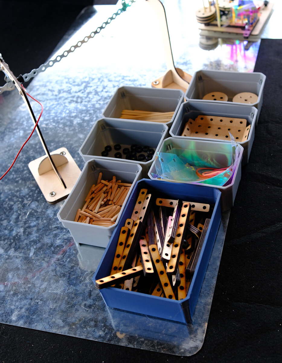
Participants use the construction elements to build their creations onto the build plates. The powered elements are: LEDs and slow moving motors, and wires to connect pylons with build plates. The structural elements are dowel rods, rubber bushings, card-sheathing, rubber bands, dichroic film, and pulleys.
Card Sheathing
- Card sheathing can be lasercut out of whatever size cardstock you have from the [card sheathing svg on gitlab] (https://gitlab.com/playing-with-the-sun/PWTS-digiFabFiles/-/raw/main/solarpunkfutures/card-sheathing.svg). With a minor increase in power, you can usually cut several sheets at a time. Quantity should be about 2-3 per build plate. You may have to poke out a lot of holes with dowel rods - I had my kids help while we watched cartoons.
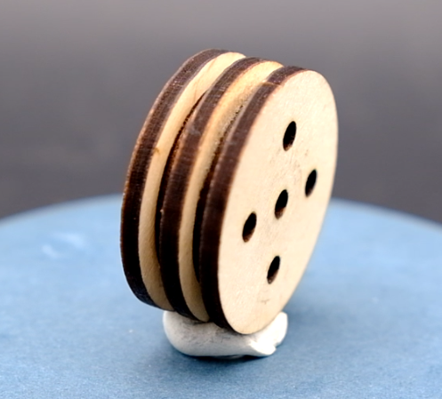
Pulleys
-
Pulleys consist of 3 large round plates and two smaller inside plates, all in the same pulley.svg file. Quantities are about two pulleys per build plate.
-
Use fast curing craft or wood glue, and be ready to clamp or place them under something heavy while they cure.
-
Put glue on both sides of the inside plates. Keeping the holes aligned, stack the plates large / small / large / small / large. Place 2 or 3 dowel rods through all the plates to make sure the alignment is correct, and then squeez the plates together hard while you remove the dowels so they don't shift.
Dichroic Film
- Cut the dichroic film into largish triangles. Use a hole punch to punch holes in each corner, so participants can place dowels through them.
Dowels
-
Cut the dowels to 10 cm lengths with a fine tooth saw like a jeweler's saw or hacksaw. You should be able to cut many at a time if you can clamp them right. It's also possible to just cut them with metal shears.
-
Place each end of the 10 cm length dowels into the pencil sharpener to shave off a little bit and make the end slightly conical. Sharpen both ends just enough to so that they're easy to insert into a build plate or a beam. Don't sharpen them to a point like a pencil.
Beams
-
Cut a few beams from 6mm plywood or mdf. Make sure that the beams fit "lightly snug" into the holes: not too tight so that they're hard to pull out of two or three beams stacked together, or too hard to twist, but not so loose that they won't hold things straight. Adjust hole size as necessary before cutting the rest.
-
Quantities should be about 8 sets of beams (a "Set" in the svg file: 1x7 hole, 2x5 hole, 2x3 hole lengths) per build plate, but you can probably get away with a little less. I just hate to run out of parts when people are building.
-
These may require poking out all the "holes" left after lasercutting - a good thing to do with the kids while listening to a podcast.
Pylon Cables
Pylon cables connect the pylons to the positive rail of the build plates, using push rivets to hold the ring connectors in place. You need 1 per build plate.
-
Cut 30 cm lengths of red wire, and strip both ends.
-
Crimp on ring connectors on both ends.
LED Lights
-
Cut the leads to about 6 cm and strip the ends. Keep the leftover wires - you may want them for the motors.
-
Crimp a ring connector with red plastic insulation jacket onto the postive lead.
-
Tear the red jacket off of a ring connector with needle nose pliers, so only the metal crimp connector remains, and then crimp that to the negative (black) lead.
-
Once crimped, add some solder to each connector make sure the wires hold onto the crimped on ring connectors.
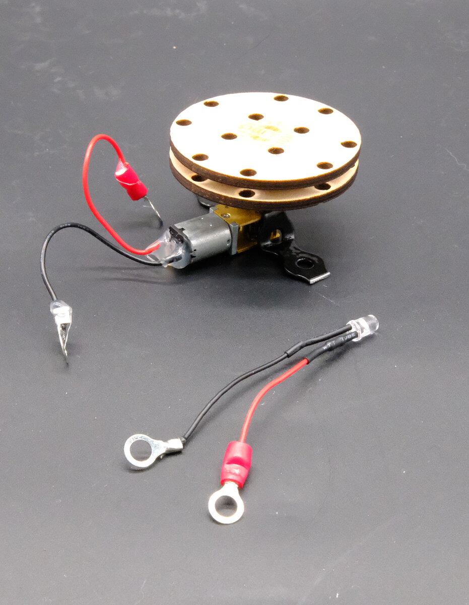
Motors
-
If the motors don't already have leads attached, you can use the excess wire cut from the LEDs, about 6 cm. Strip both ends and solder wires onto the motor terminals. Polarity doesn't really matter here, but it might be a good idea to be consistent with wire color choices.
-
Put hot glue around the terminals where the wires connect to the motor to provide some strain relief, so the wires don't break from the terminals.
-
Crimp a ring connector with red plastic insulation jacket onto the postive lead.
-
Tear the red jacket off of a ring connector with needle nose pliers, so only the metal crimp connector remains, and then crimp that to the negative (black) lead.
-
Solder the leads onto the crimp connectors to make sure they hold in place.
-
Cut a length of metal plumber's strap to 5 holes. Trim each end just outside of the hole, so the width is as short as possible. (This is to keep the strap from being able to create a short between the positive and negative rails of the build plate.)
-
Place the motor's axle through the center hole of the strap. Using pliers, bend it 90 degrees downwards around each side of the motor body. Then grip it with pliers where it passes the bottom of the motor (the opposite side of where the shaft comes out), and bend it 90 degrees away from the motor.
-
You now have a mounting plate that fits around the motor to hold it in place, so the bottom can be "dootered" or push-riveted into the holes in the build plate. Proportions and distances matter here, so test to see how well the holes align, and bend the strap as necessary to get things close enough.
-
Lasercut the motor drive wheels from the gitlab repository. Best to build one to check hole tolerance with your beams (lightly snug) before cutting the rest.
-
Make sure the mounting plate is in place on the motor. Place white or wood glue on both sides of the smaller inner plate. Place the bottom large plate (with the D shaped hole) onto the shaft of the motor, then the smaller inner plate, then the outer plate (with logo and no "D" hole.) Squish two lower plates up close to the top plate. Place dowels in several holes to make sure they stand perpendicular, and the plate holes are aligned. You may wish to use spring clamps to ensure a strong glue bond.
Solar Panel
A solar panel with a USB A output will provide power at 5 volts. The easiest way to get it is to cut a USB cable open and look for the black and red wire. Connect the black wire to the steel ground plates, and the red wire to one of the pylons without short detection, so it feeds power into the power loop. You can use ring connectors and push rivets to make the connection.
If you want to use a larger solar panel rated at DC 12 Volts, you need to have it power a voltage regulator that will step the power down to 5 volts DC. These can be found on aliexpress or other electronics stores.
Questions? Corrections?
Write to pwts@amosamos.net if you are stuck and need help. If you find an error in this documentation / instructions, feel free to edit the markdown doc and submit a pull request, if you are familiar with git. https://gitlab.com/playing-with-the-sun/pwts-docs
Contributors / Acknowledgements
Andrew Amondson was creative producer for the first run of this activity, and contributed the background mountainscape and airship designs, as well as acting as creative producer and co-facilitator for the Berlin debut. Sebastian Martin gave valuable feedback and suggestions in the early design phases of this activity. Lander Blanton did many iterations of great CAD work on the Pylon designs.
The Experiencing, Experimenting, Reflecting Project, funded by Carlsberg Foundation and led by Andreas Roepstorff, provided support and inspiration throughout the project, including Sophie Erlund and the team from Studio Olafur Eliasson who joined in the January 2014 workshop on Playing with the Sun.