Motors
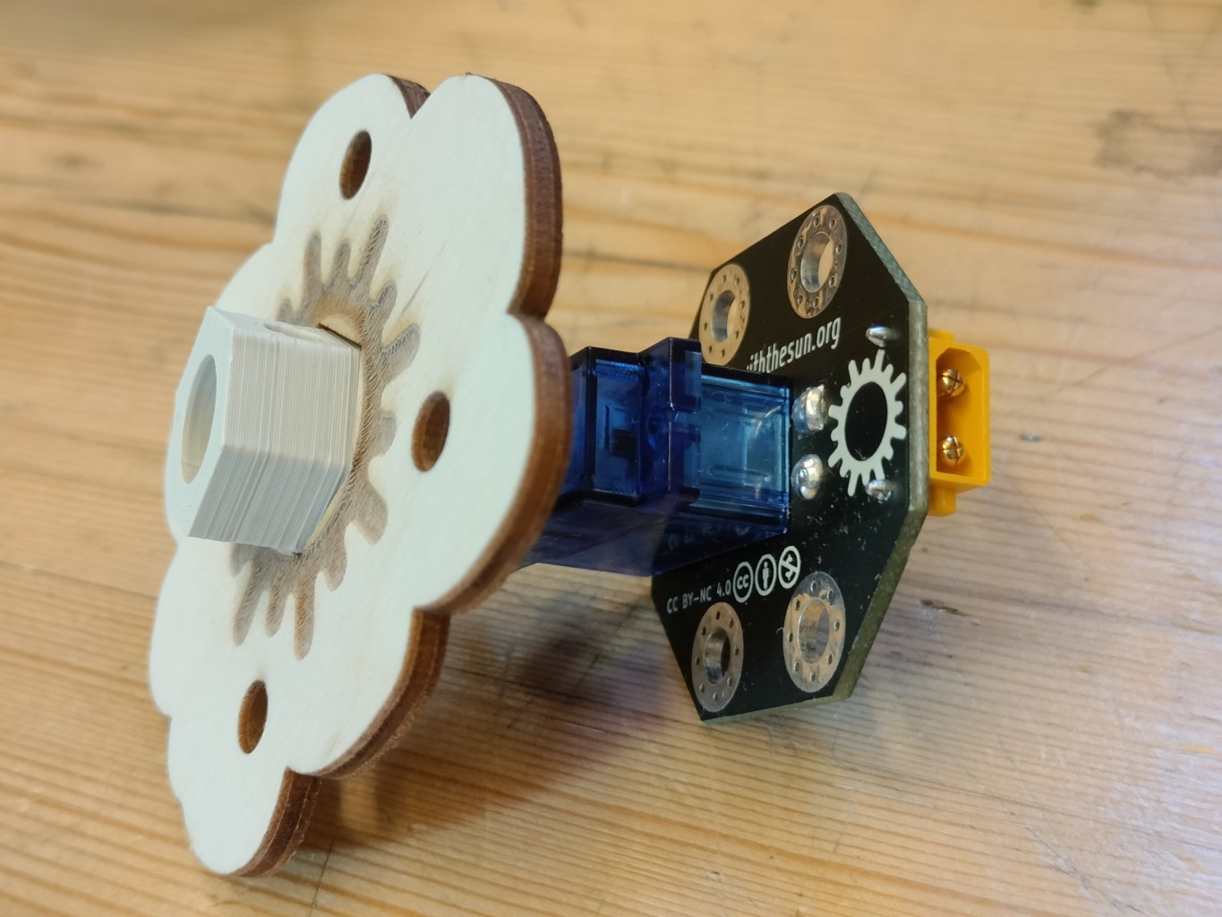
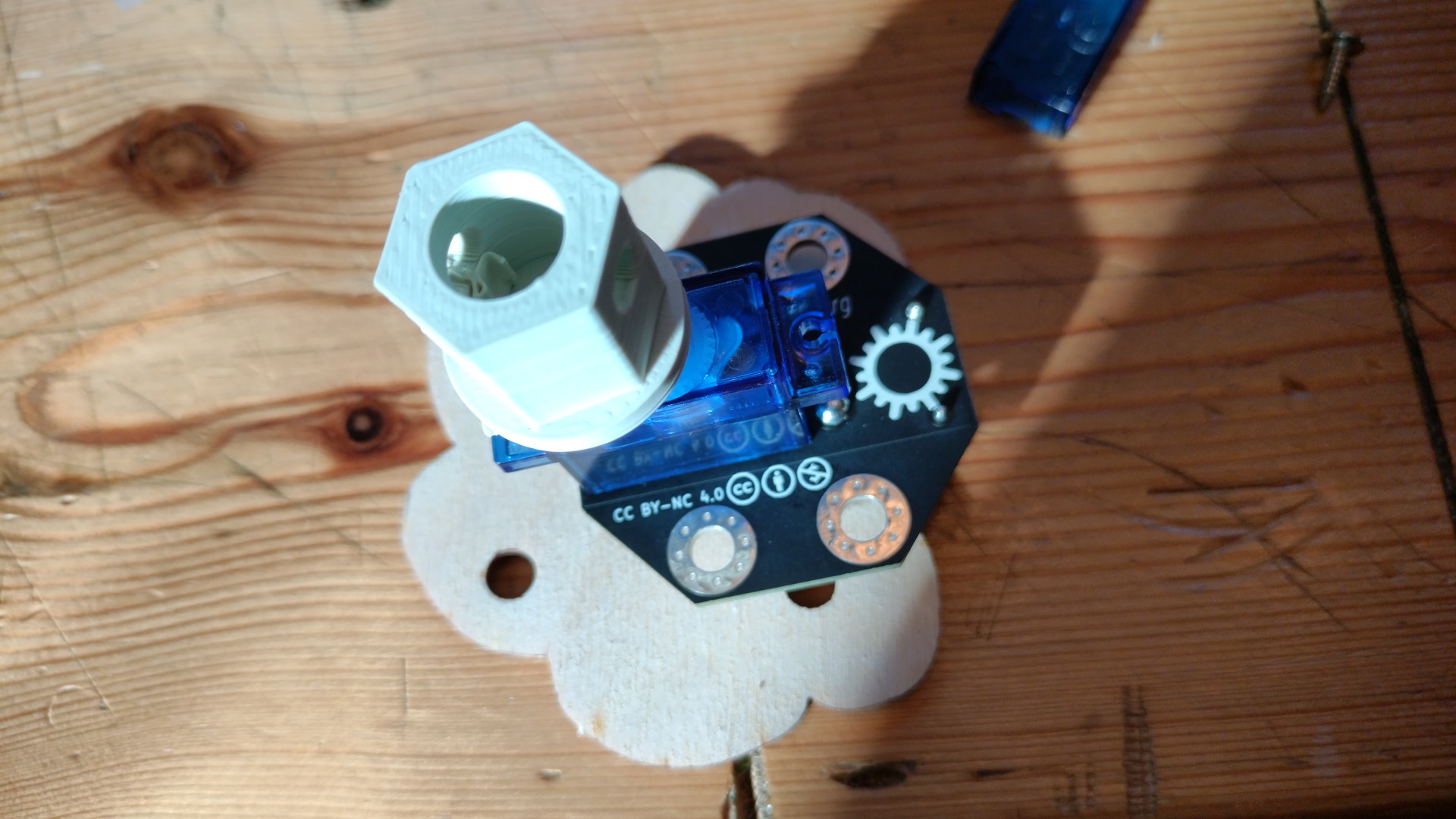
The motor turns power into rotational motion. The more power it gets, the faster it turns. It has a hexagonal hub on the front which allows you to place different kinds of wooden lasercut "wheel-like" shapes onto it, to explore different kinds of motion, or even to use bent plumber's strap as a wheel. It has a switch on the back to reverse the motor direction. To try it out, just plug a power source like a crank generator or a solar panel into its input.
Sourcing Parts
- Motor board (rev. 3). Note: This can be produced from the kicad files in our Gitlab repository, but it's not easy to do. We're working on a simpler solution.
- DC Motor in Micro Servo body from Adafruit or one of its worldwide distributors, like Mouser in Europe
3D Printed Wheel Hubs
The 3D printed wheel hubs are screwed onto the drive spline of the DC Motor in Micro Servo body. You can find the necessary files along with instructions on how to print them in this folder on our Gitlab digital files for fabrication repository.
Laser cut wooden wheels
These wooden wheel-ish shapes have hexagonal holes that allow them to fit onto the 3D printed wheel hub. You can find the files to lasercut them along with notes in this folder on our Gitlab digital files for fabrication repository
Assembly
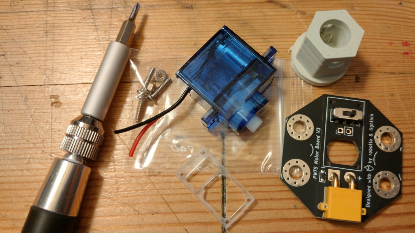
Tools:
- soldering iron
- small phillips screwdriver
- wire stripper (for very small and short wires - something like these
- side cutters
Assembly Instructions:
- Clip off the motor's power lead and unscrew the back plate of the gear motor with a small phillips head screwdriver. Be careful to keep the screws - we'll be using them.
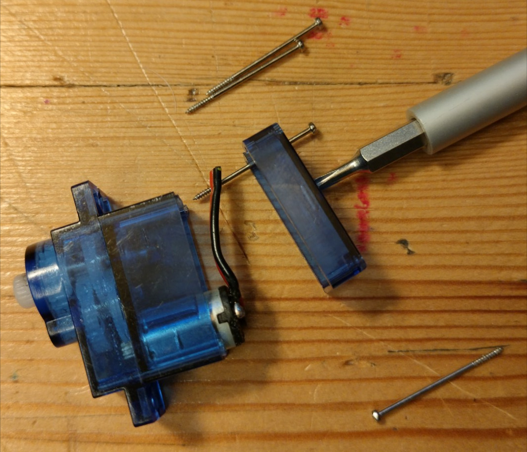
- Using the sidecuttes or some pliers with a wirecutter, clip 2mm off of the end of each of the 4 back plate screws. Shortening them this way prevents them from coming out of the face of the motor casing when we screw them in later.
- Position the motorboard onto the back of the motor such that the motor fits in the hole. Cut and strip the motor wires so that they reach the solder pads on the motor board, and solder them in.
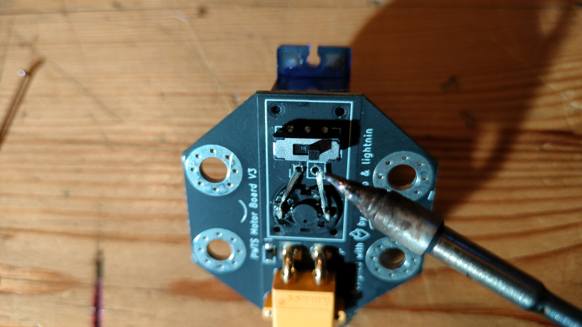
- Using the 4 clipped screws, attach the circuit board to the motor case. Make the screws snug but be careful not to strip them.
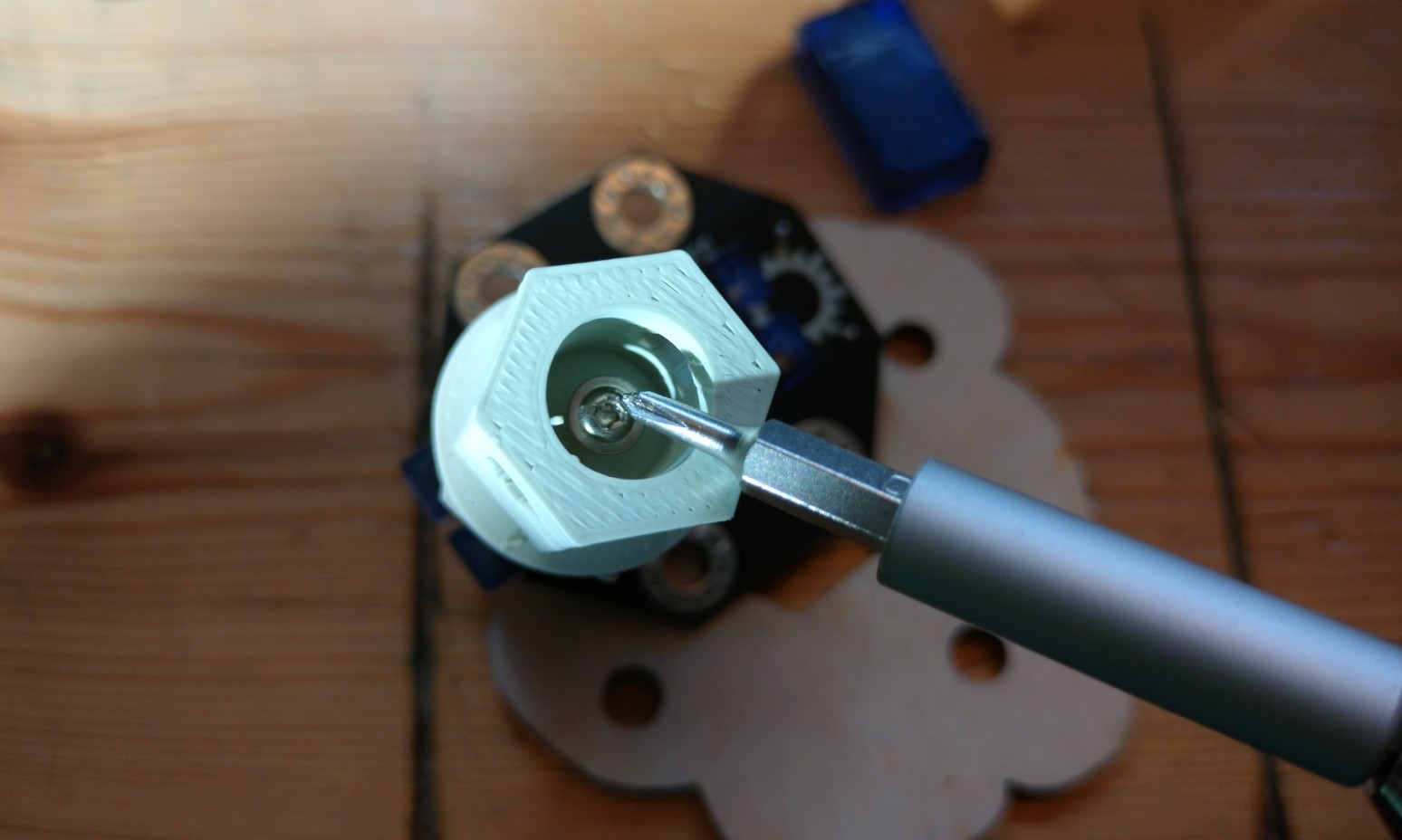
- Place the motorboard onto a wooden wheel with the switch inside its hexagonal hole, so that you can press down hard on the hub to get it to seat onto the spline of the DC motor. Then use the cap screw that comes with the DC motor to screw it into the hub.
Desired Improvements
- It would be cool if we could get the slide switch to stick out more, so that with the cable crawler activity you could have it drive to the end of a cable, knock the switch to reverse the motor direction, and then go to the other end of the cable / repeat / etc.
- There might be better motors out there. The greater the torque and useful voltage range, the better. But it has to be able to tolerate being forcibly stalled by kids holding it when it wants to turn. And it has to stand being back driven sometimes cruely.
- It might be worth exploring a user-tunable potentiometer so that the user can control the rate at which the motor uses power and its output speed. It'd have to be a hardy pot that can take a lot of twists, and output would have to be bounded within a range where it always moves at least a little provided power is say >2 V. We don't want people getting confused when they plug things in but their circuit doesn't work just because the pot was left tuned down too low. This risk of added complexity leading to confusion is a big part of why we haven't done this yet.
Past Revisions
- The first PwtS kit motor board was just a blue motor with an XT30 connector glued onto it. But we've gone through a lot of hub / wheel designs, for which Jane deserves a medal. The iterative process showed us that:
- The splined hub on the blue motor doesn't make for a reliable press fit, at least not that we can hit the necessary tolerances for with a lasercutter. Having the wooden wheels be changeable / removable is important. So that's why we went with the large 3D printed hexagonal hub screwed into the motor + snap rivet design.
- It's also important that when the motor is running with no "wheel" attached, you can still see that its turning. The 3d printed hub rotation is much more visible than the white motor spline without anything attached, which you might not notice was even turning.