Solar Panels
These solar panels provide approximately .5 Watts of power at 5V in full sunlight. They can be stacked to create more power when needed. With enough power, they can be used to power motors directly. Or you can use them with a solarengine in between the panel and the motor to get a larger working range of light. They can also be used to charge a powerpack, but that takes some time even in full sun, as the powerpacks hold a lot of energy.
Like most, these solar panels generate most of their power in the visible through near infrared spectrum. Therefore they make less power from artifical lighting than from the sun because most indoor lighting has a limited output spectrum. LED artificial lighting is the weakest because LEDs only generate a limited spectrum of light (which is why they are so efficient.) Fluorescents make a tad more, but old fashioned halogen or tungsten lights provide the most power because they emit light in the visible and near infrared range.
Parts and Tools
- .5 watt 5V Volt Solar panel Seeed Studios.
- Right Angle PCB Mount Female XT30 Connector, XT30PW-F (technically this is female, but it looks like a plug). Mounted on the bottom of the panel, this is where the power comes out.
- Right Angle PCB Mount Male XT30 Connector, XT30PW-M (technically it is male - but it looks like a socket). At the top of the panel, this is where additional panels can be attached to generate more power.
- 3mm plywood for lasercutting the solar panel back plate
- VHB Tape 4941 or similar, approx. 12mm wide. This is a very strong permanent acrylic bonding double sided tape.
- Zip ties and hot glue.
Tools Needed:
- Soldering iron and solder
- Wire stripper
- Hot glue gun
Assembly Instructions:
-
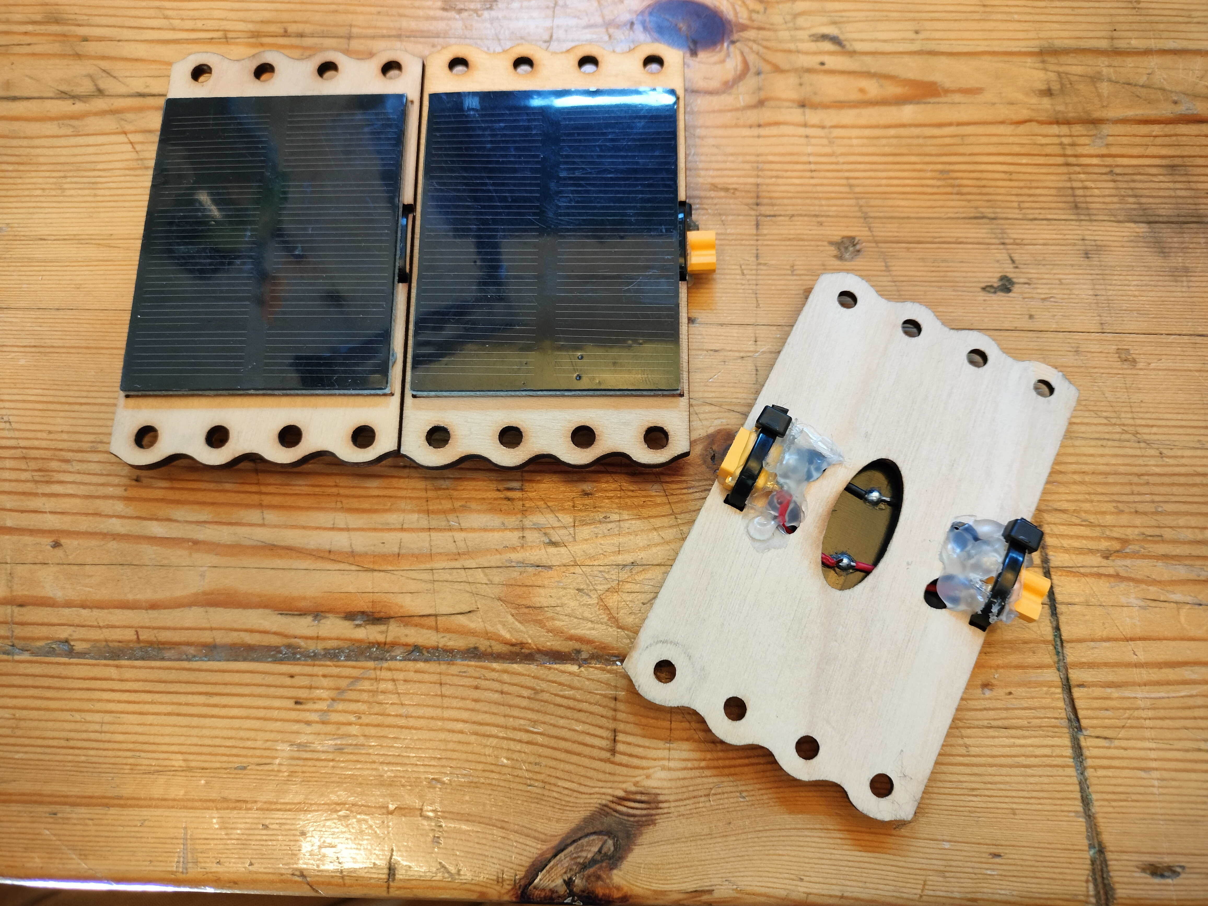
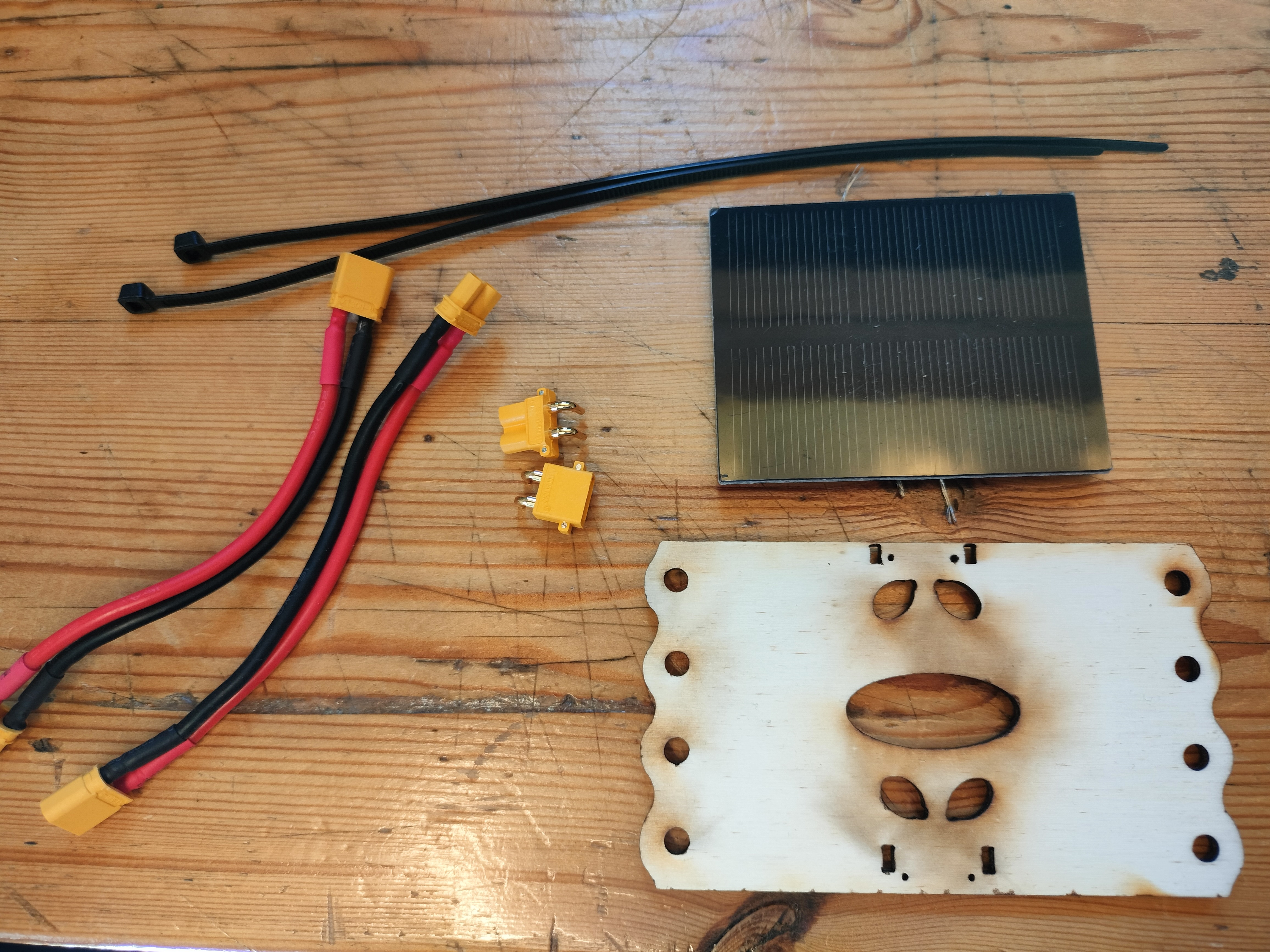
Lasercut the panel frames from 3mm plywood, using the panel-backing-3.0.svg file located in the Gitlab repository. You should have the parts shown here.
-
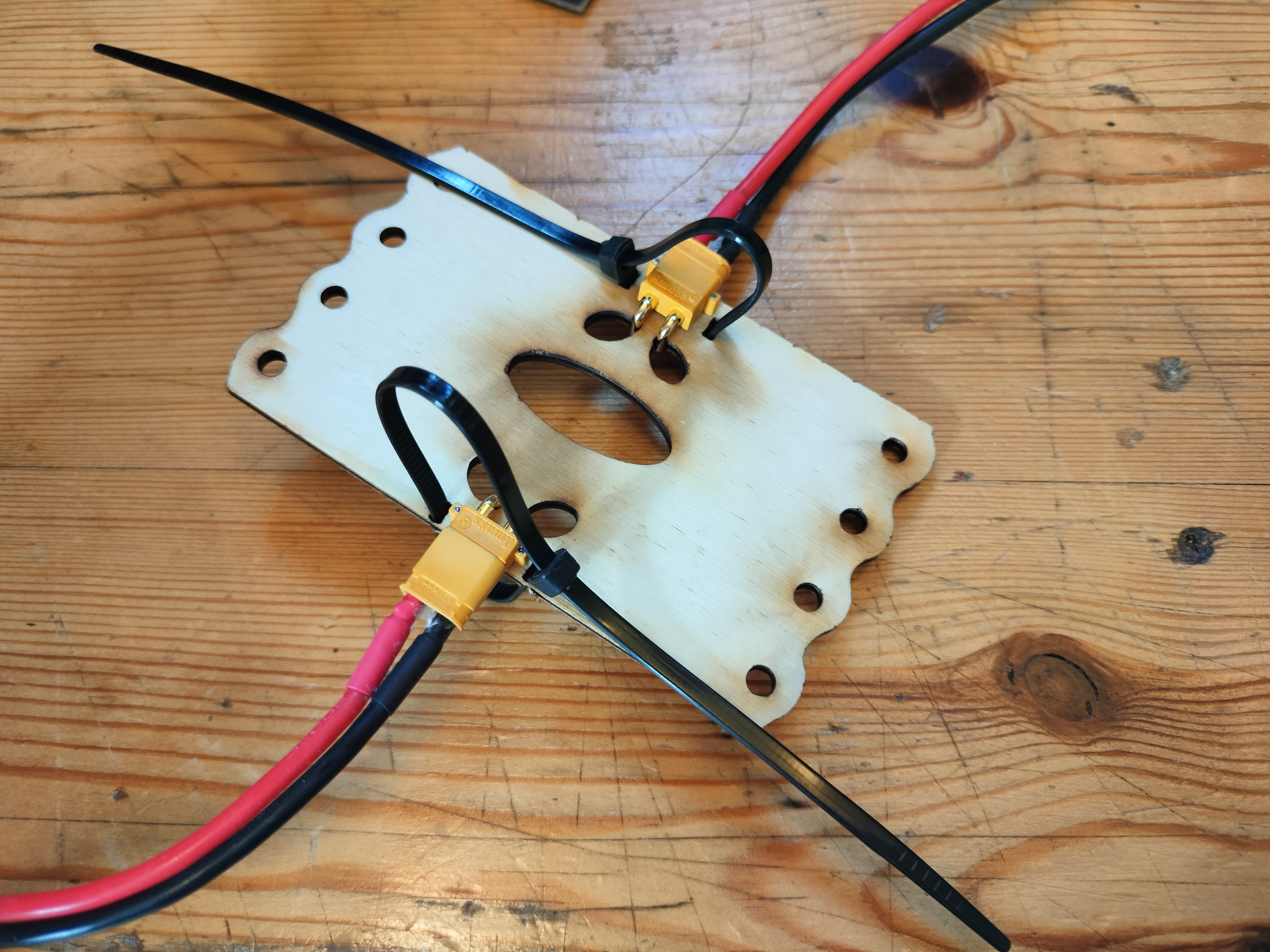
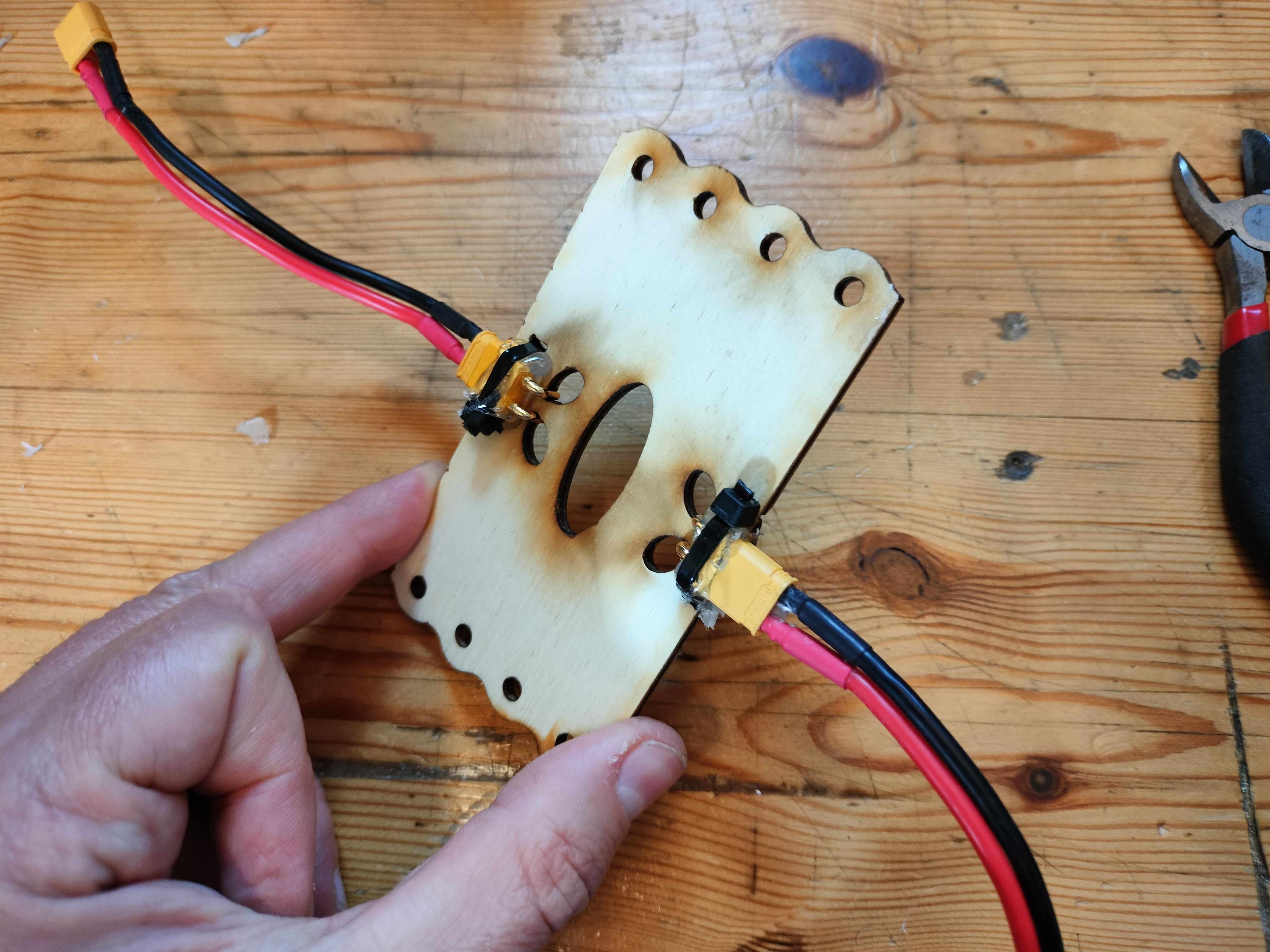
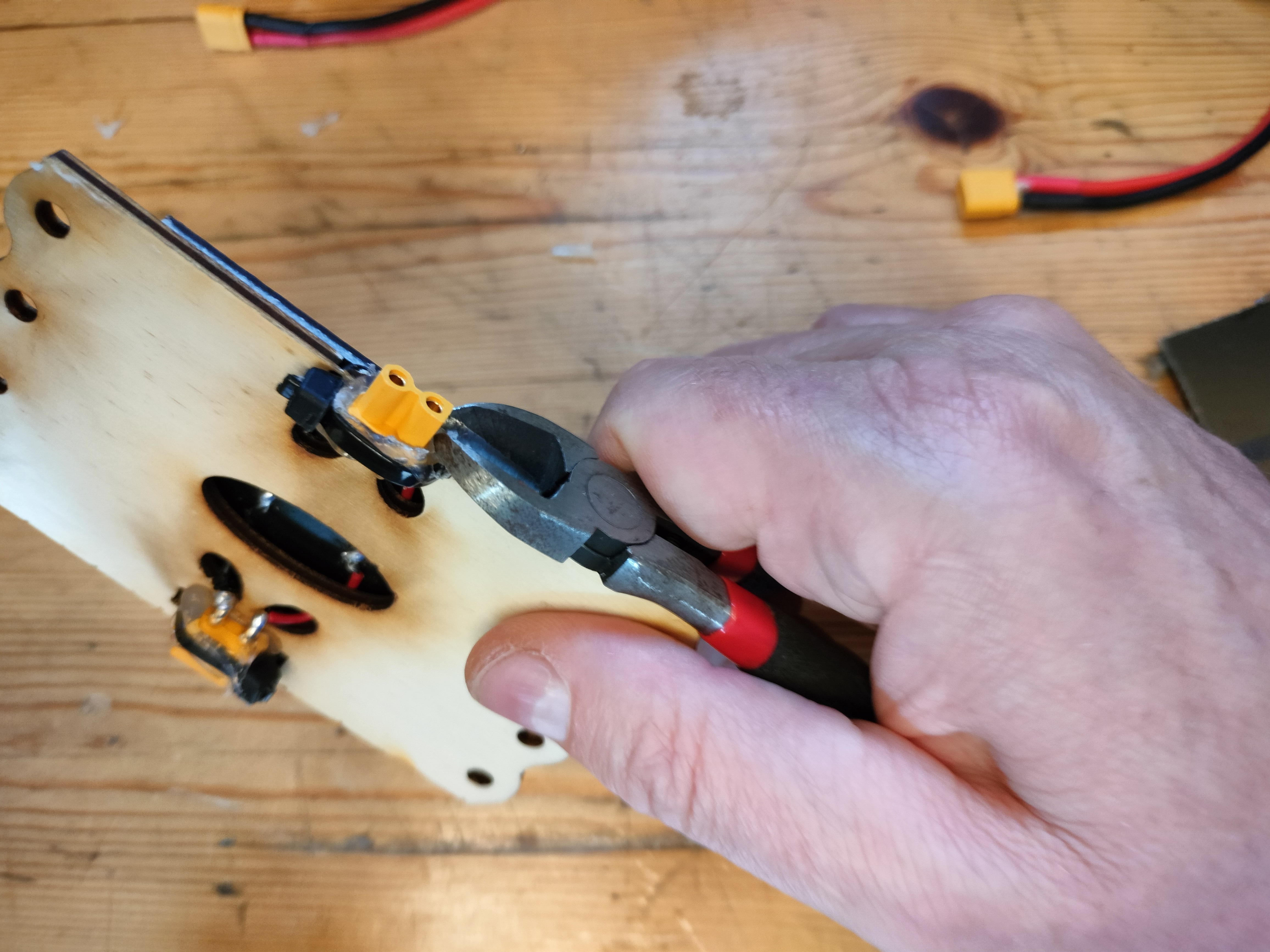
Now take your two different XT30 connectors and connect each of them to one of your XT30 patch cables, to protect the connector from getting glue on it while we work with it. The connectors have little pins on the bottom in addition to the larger electrical "legs" that fit into the back of the solar panel frame. Be sure to place them on the opposite side of the solar panel back plate, the side without the inscribed text. For each connector place a zip tie through the frame as shown, but don't tighten it yet. Make sure the zip tie "gate" is on the same side as the connectors, flush with the solar panel back plate.
-
Remove each connector and spread a bead of hot glue under where the connector fits, and then stick it back in place while the glue is still hot. This forms a bed of glue for the connector to fit onto. Now draw a bead across the top of each connector, where the zip tie will contact it when tightened. Tighten the zip tie very tightly, making sure there is no slack on either side of the panel. The hot glue is there to form a bed that keeps things in place once it cools, and the zip tie should hold everything firmly in place. Once the hot glue has cooled you can remove the Xt30 patch cables, and clip the end off the zip tie.
-
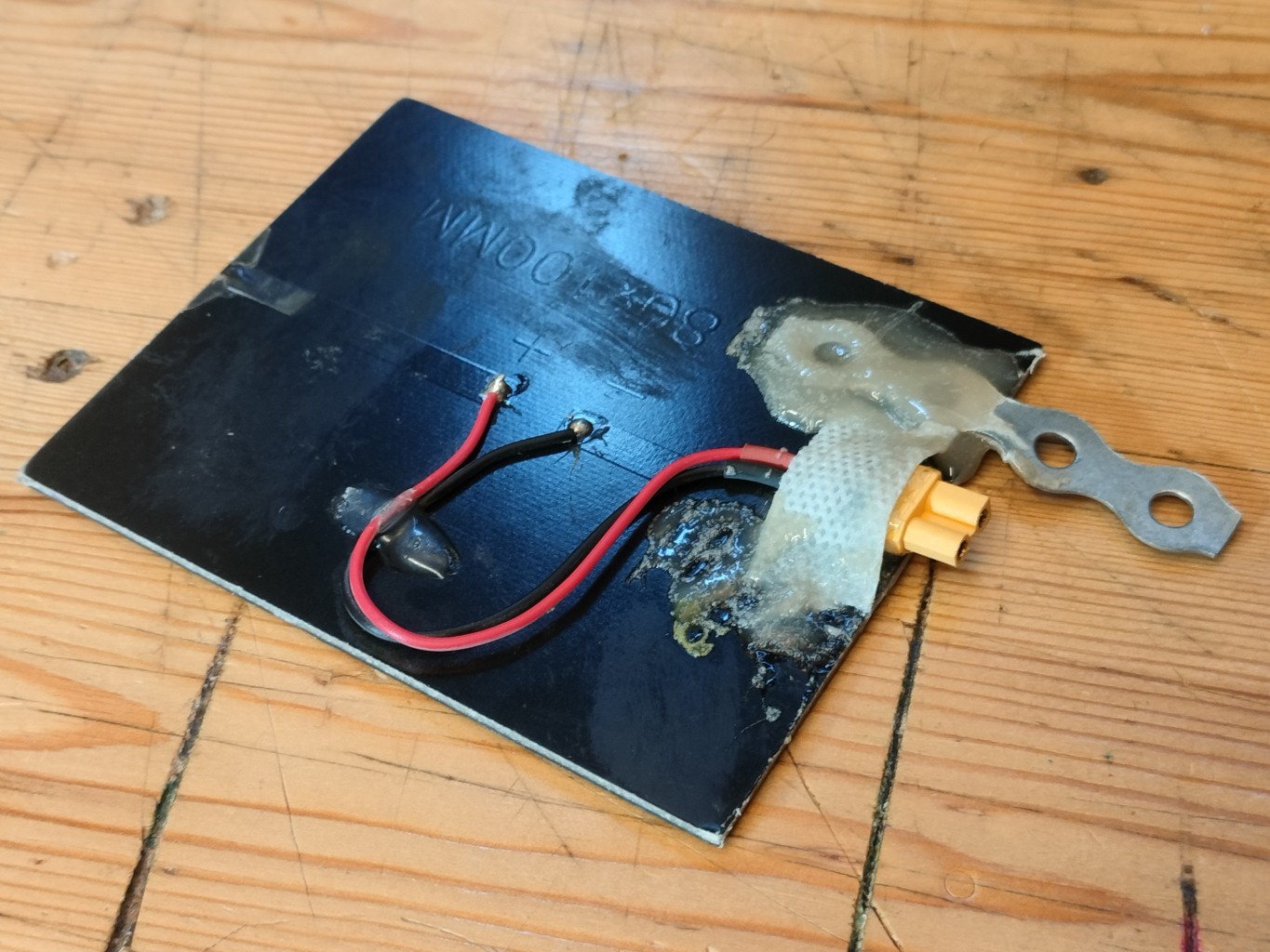
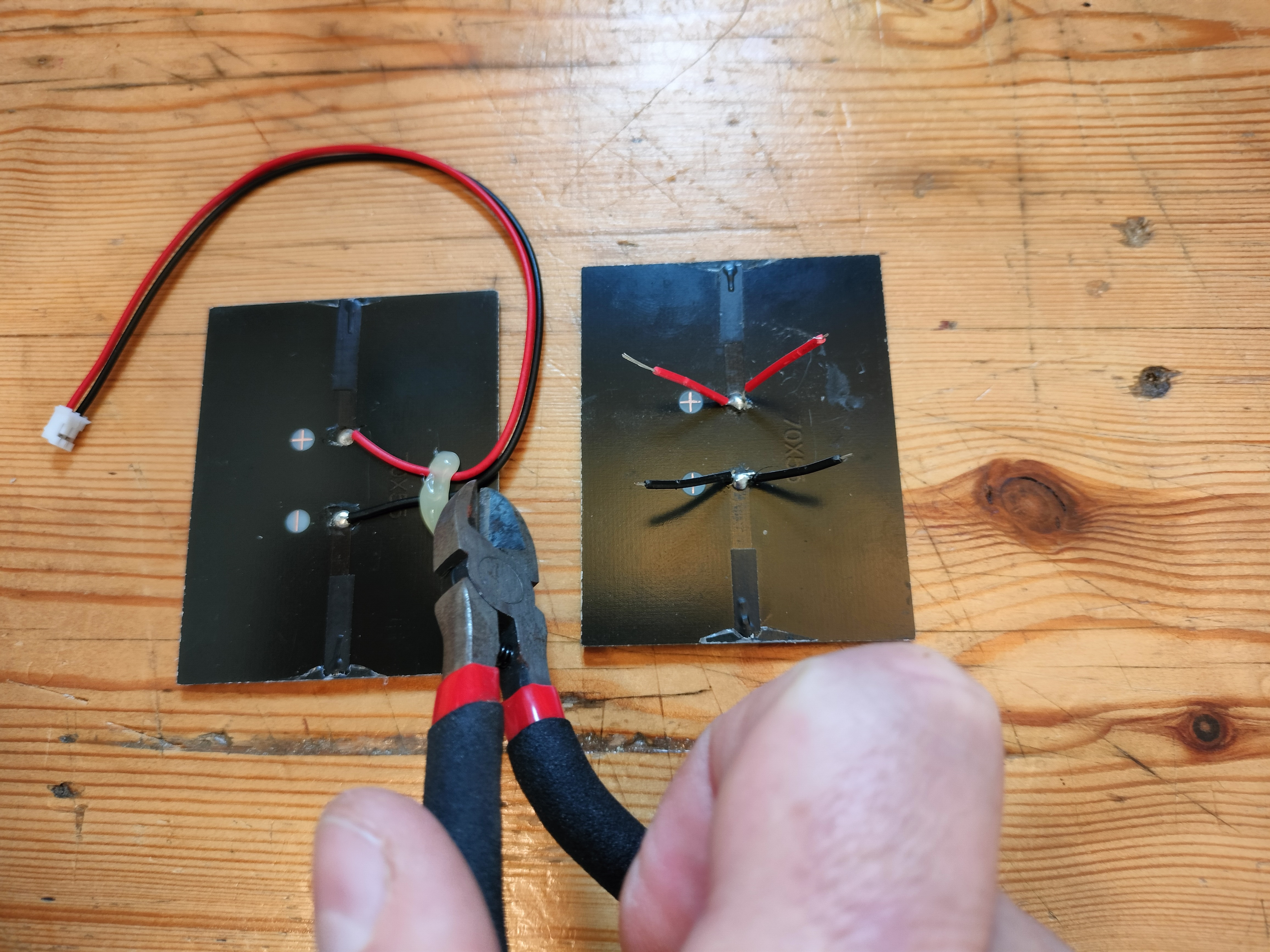
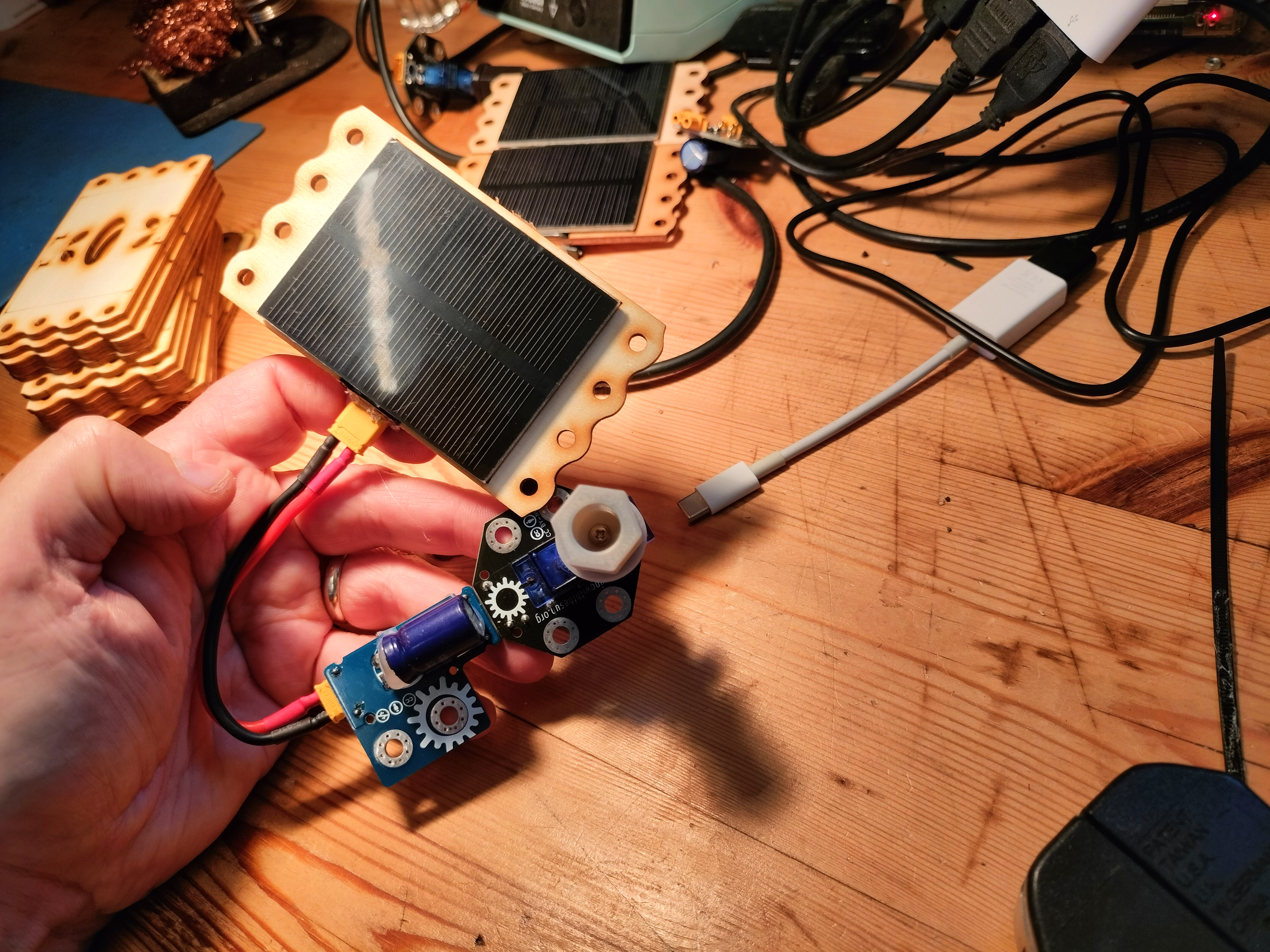
The solar panels come with a wired connector soldered onto the pads. Cut both wires to the length required to reach the legs of the XT30 connectors, and strip a bit of the insulation from the ends. From the wire you've cut free, cut another equal length of red and black, and strip the ends. Solder this wire to the solar panel's positve and negative pads as well - red on positive, black on negative. When you are done, it should look like the panel on the right in the image below.
-
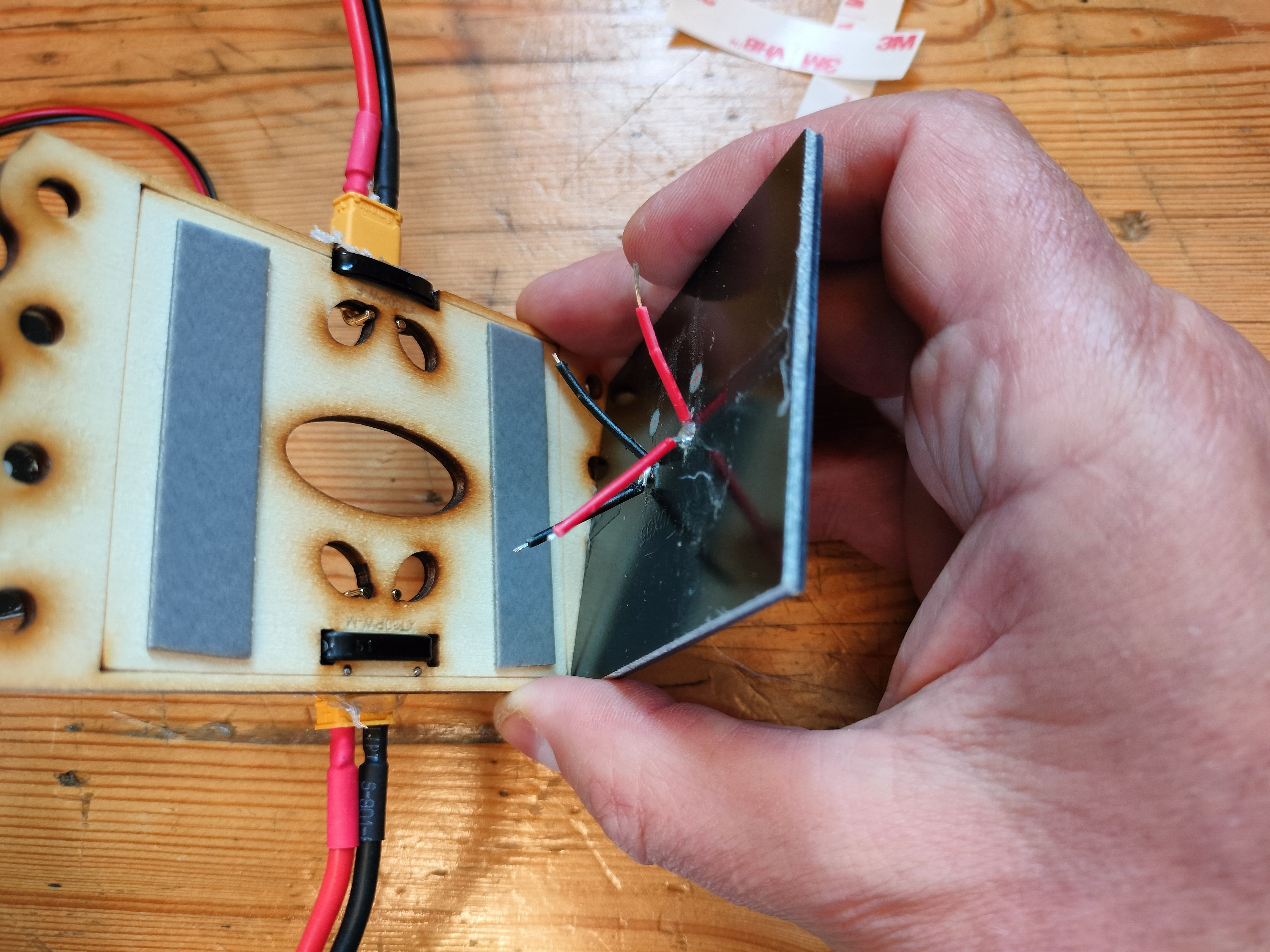
Flip the panel frame over and apply VHB tape to the area within the outlined frame. Bend the wires so that they will come up through the oval holes in the solar panel back plate and reach the legs of the XT30 connectors. Make sure the red wires will touch the + terminals of the XT30s, and the black wires the negative terminals - if not then you need to rotate the panel so they will. Remove the VHB tape backing, and hold the panel close to the back plate so you can thread the wires through the oval holes. It might help to bend the wires upward first. Before the panel touches the VHB tape, line up the solar panel with the outline etched onto the front of the panel frame. Now press the panel and the plate together firmly and wait 20 seconds so the VHB has time to make a good bond.
-
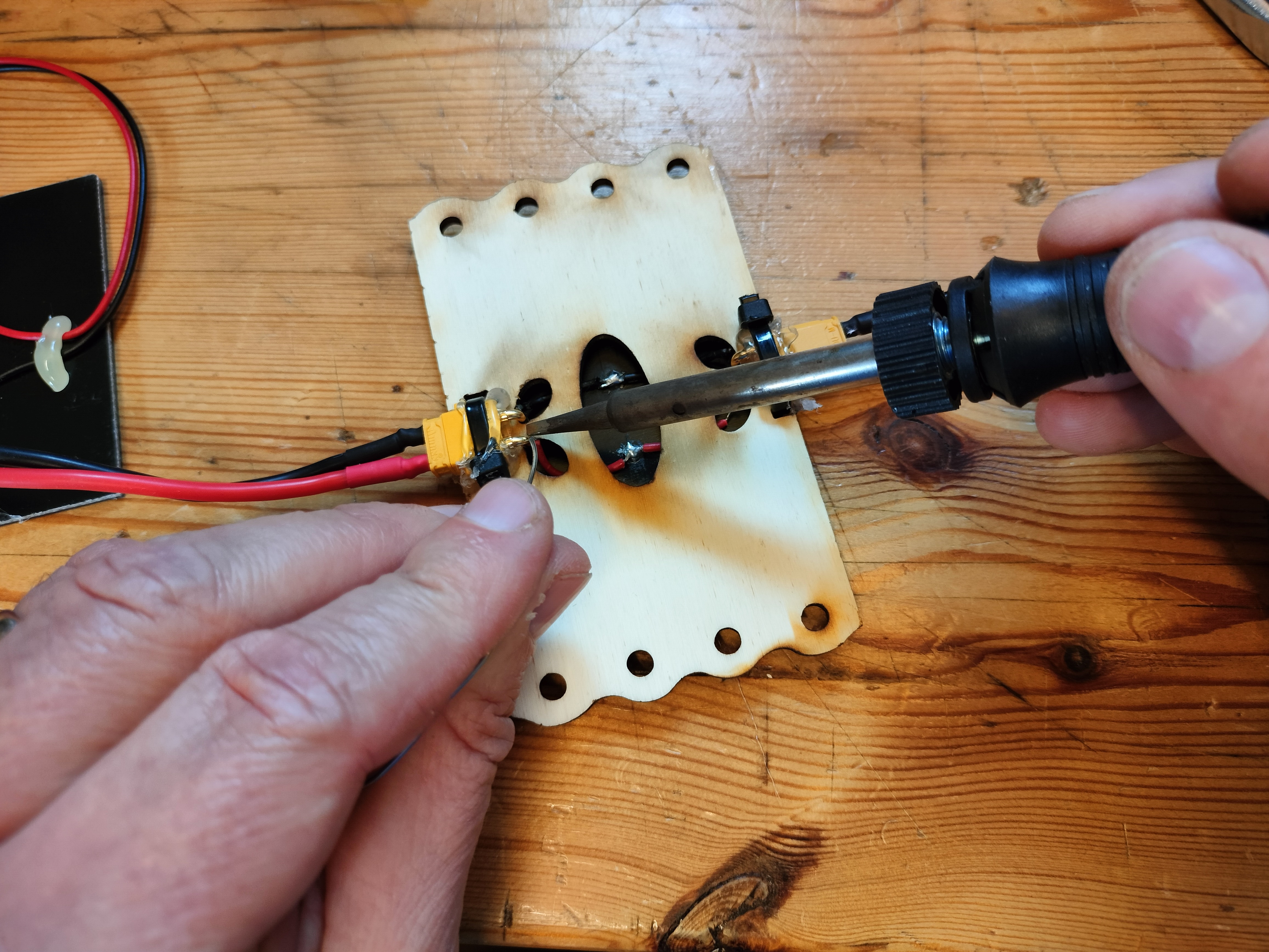
Now solder each wire to the correct terminal on each of the XT30s. If the length is too long, you may need to trim it and re-strip the end. Make sure you get the large XT30 legs hot enough for the solder to bond well to them.
-
Remove the XT30 patch cables, and trim away an excess hot glue that would otherwise keep the connection from being tight. The panel should fit tightly against another identical panel when plugged in.
-
Test your panel by plugging it into a motor and giving it full sun. Add another panel to make sure the male connector works (it should go faster with two panels than with only one). Once you are sure the soldered connections are working as they should, cover them with hot glue. Your panel should be ready to go!
Thanks to Jørgen Tietze of Vejle Library for the (great!) idea of using a zip tie to anchor the connector.
Desired Improvements
- Round panels would fit the aesthetic better.
- There are solar panels that work better with indoor light frequencies, but we haven't found any that are inexpensive. It would be nice if we could find some that can be used with LED work lights indoors on rainy days. This would give us a lot more flexibility when planning workshops.
Past Revisions
- The second revision used a 1 watt solar panel, but had only one connector, so you couldn't stack the panels to get more power.
- The first revision just had the outputs soldered to an XT30 connector, slathered in epoxy. ( These had Left and Right versions because the plumber's strap was either left or right of the connector, which created a problem if you need one type but couldn't immediately find it. This is why current revisions have the connector at center.