Hand Crank Generator rev. 4
The hand crank generator makes power when you crank it. Just plug it into a motor and crank to see the motor turn. You can also use it anywhere else that a power source is needed -- like to charge up a powerpack.
Sourcing Parts
The Hand Crank Generator is composed of a generator (a driven DC gear motor), a rectifier that allows the generator to make power whichever way it is cranked, and two zener diodes to limit the output to 5 volts. You'll find links below, but don't think you need these exact parts: anything electrically equivalent will work. If you find better parts, or a better way to build a generator, that's great! Just tell us so we can update this page so everyone else benefit.
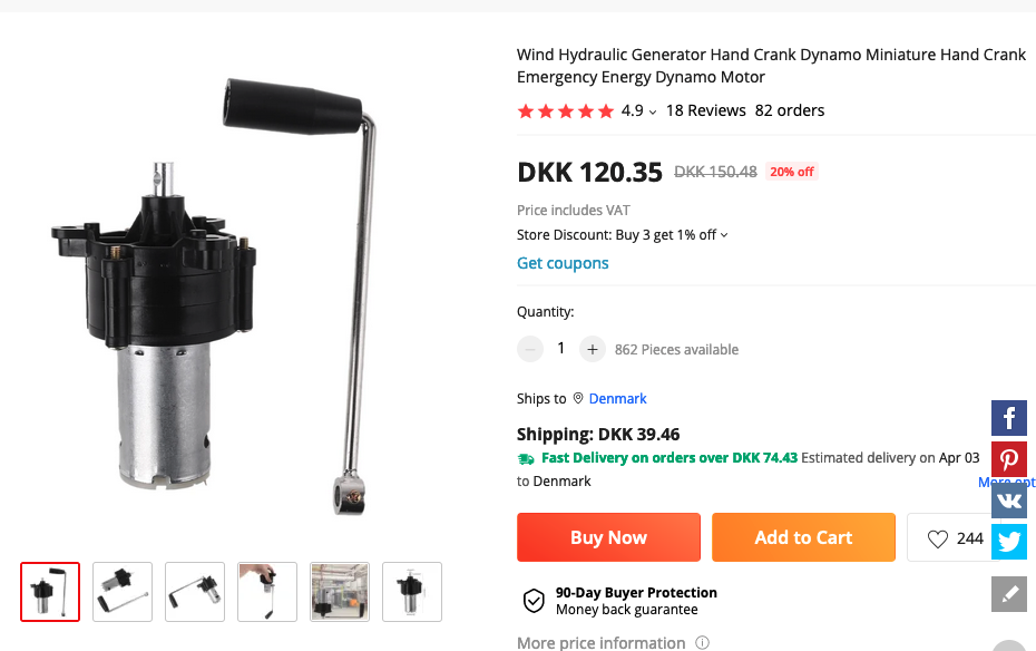
Hand crank dynamo
A robust hand crank that spits out power in the roughly 12 Volt / 20 Watt range. The ones shown below appear to be widely available at low cost on Ebay and many other vendors. Make sure to buy one that includes a crank arm, as there doesn't appear to be an easy way to make and attach one short of doing difficult metalwork.
Vendors:
- Aliexpress
- EBay
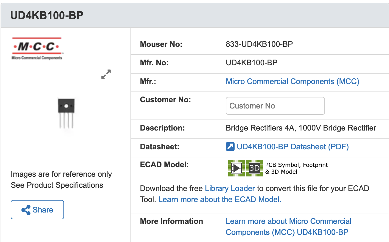
Bridge Rectifier
The bridge rectifier takes positive or negative power from the generator and converts it to a single polarity of output. This allows the crank generator to work no matter which way it is cranked.
Vendors:
- Mouser
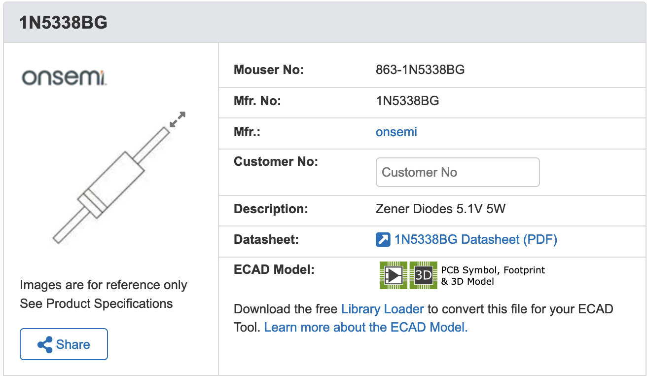
Zener Diodes
Normally a diode is like a valve that only lets power flow in one direction. Zeners are also diodes, but they're used to limit the voltage in a circuit. You put them in backwards, with the positive side on the negative wire, and up to 5.1 Volts they do what all diodes do: They don't let the power flow (backwards) through them. But if you give it anything above 5.1 volts, they do let the current flow backwards through them. That makes sure that no more than 5.1 volts comes out of the crank charger's wires, which is what we want.
Vendors:
- Mouser
Miscellaneous
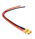
- XT30 female connector (which looks like a "plug" and not a "socket") with wires soldered on to make the output cable, or an XT30 patch cable with the male (which looks like a socket) end cut off.
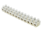
- Terminal block connectors, for joining the various elements.
- 2 x 10 cm pieces of stranded wire (14-22 gauge will do)
- 1.5 inch / 36mm inner diameter x 40mm outer diameter silicon tubing cut to about 8 cm lengths. It should just fit around the round motor body on the back of the crank generator, but you can hose clamp it on if it doesn't already fit tightly enough.
- 7 hole length of plumber's strap, to crimp end of tube.
- small bolt that fits through the holes in the plumber's strap (approx. 4mm), nut, and a lock washer. These will keep the tube crimped at one end.
Tools you will need:
- Soldering iron
- wire strippers
- small screwdriver (for terminal block connectors)
- voltmeter (for testing output of the generator)
Assembly Instructions
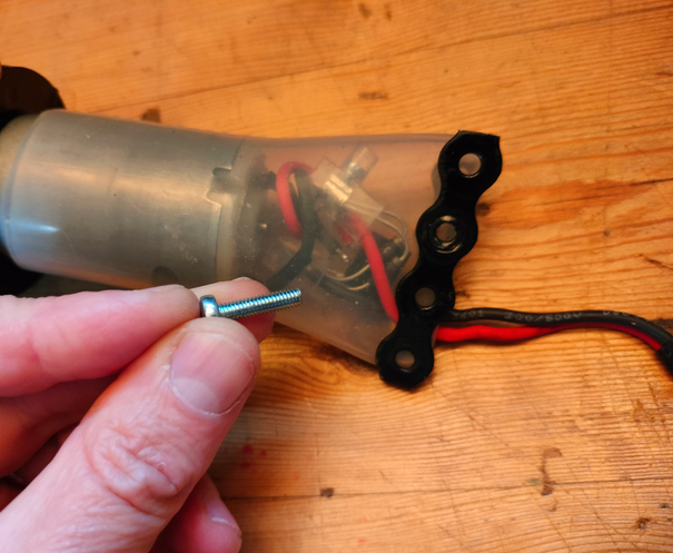
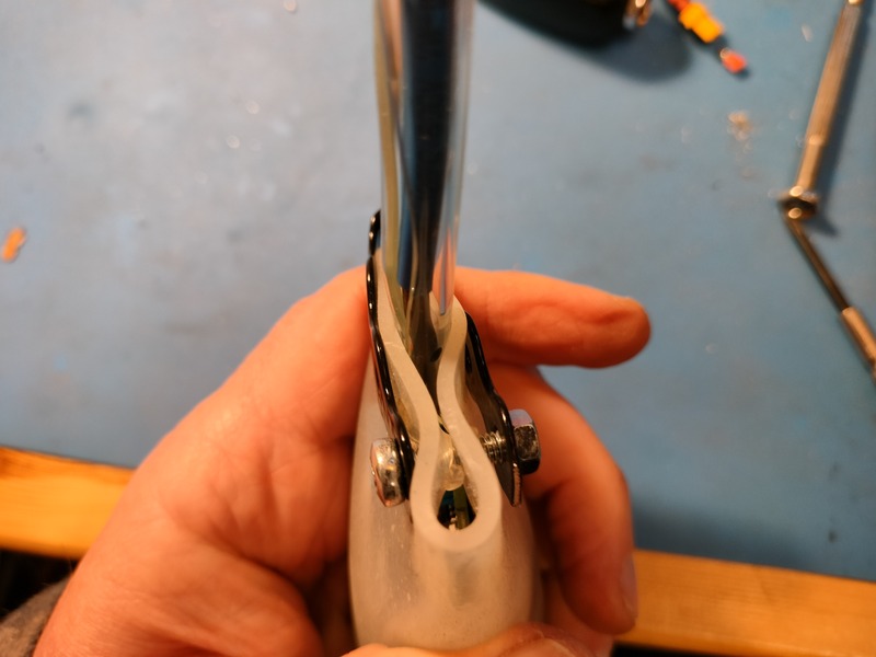
- Attach the crank to the body of the generator gear motor. If it didn't come with a bolt that fits the driveshaft hole tightly, a large cotter pin makes a good substitute. (Bolts that are too skinny tend to get sheared off.)
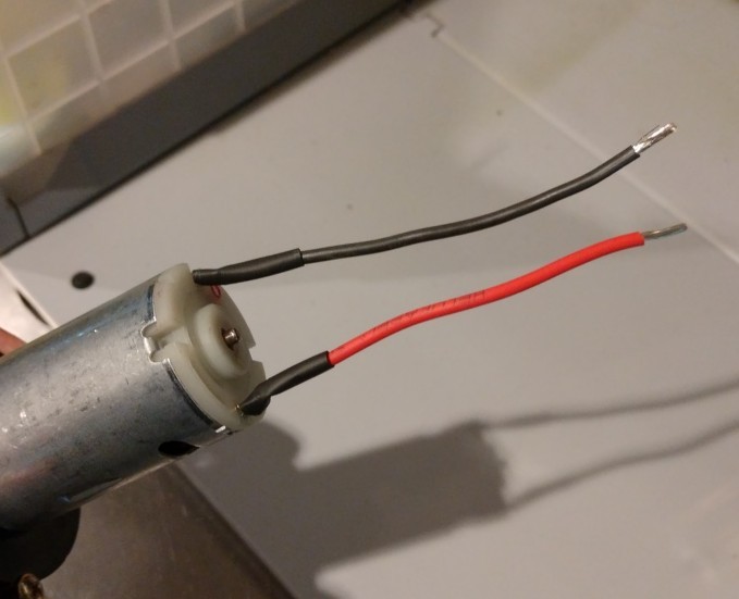
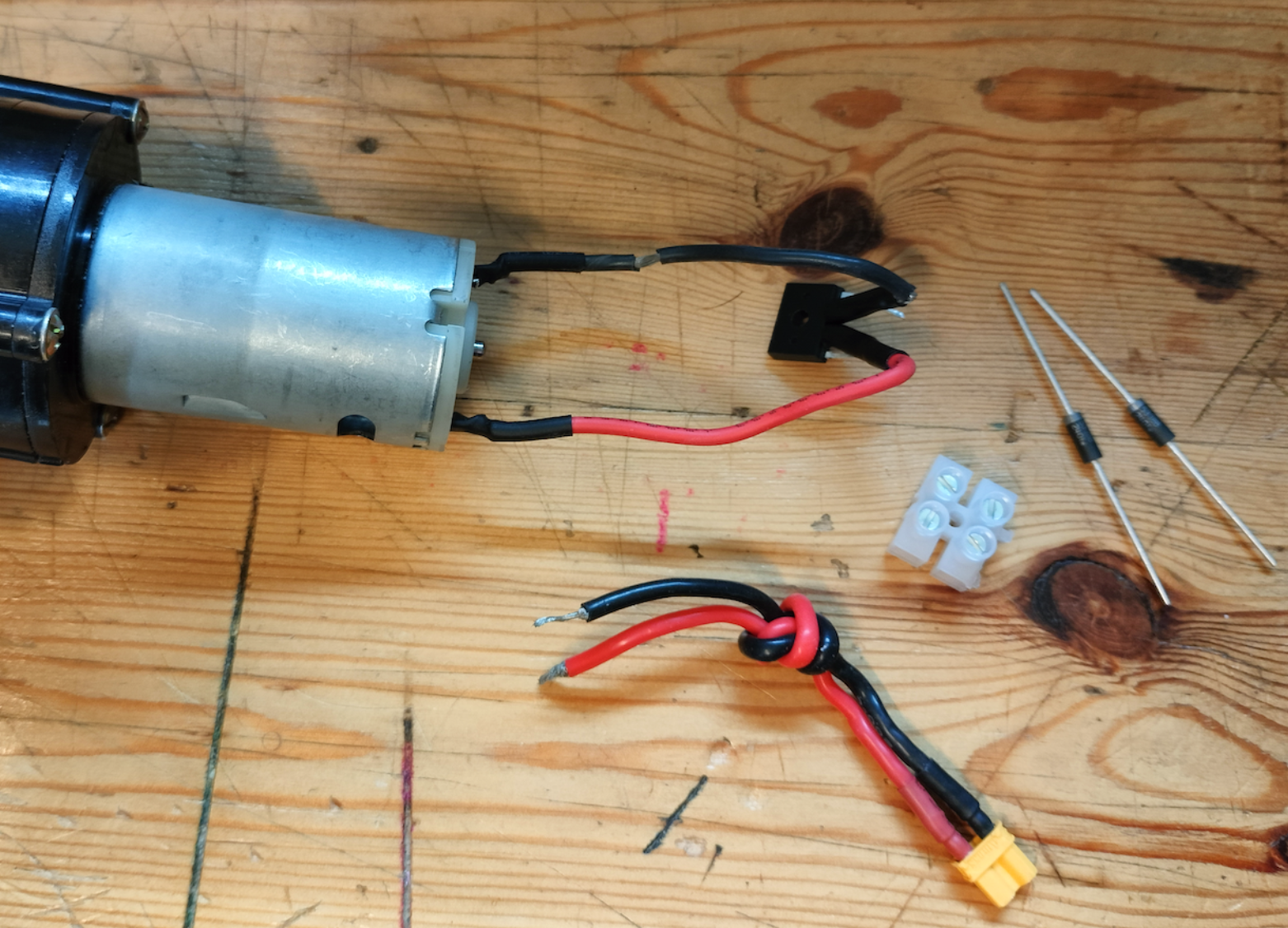
- Cut two wires (color doesn't matter) to about 3-4 cm length. Strip the insulation from both ends. Solder each one onto one of the two terminals on the back of the hand crank generator.
- Examine your bridge rectifier. Notice the small + and - symbols printed on one side of the rectifier above the two outside legs. These are the output legs of the rectifier. These need to be connected to the XT30 output lead, and polarity matters here - which means the positive leg needs to connect to the positive lead on the xt30. The two center legs have a little "~" near them. Each of these two legs need to be connected to the wires coming from the generator, but in this case polarity does not matter. You can jam the legs into the wire and put a little bit of solder on, or you can use terminal block connectors.
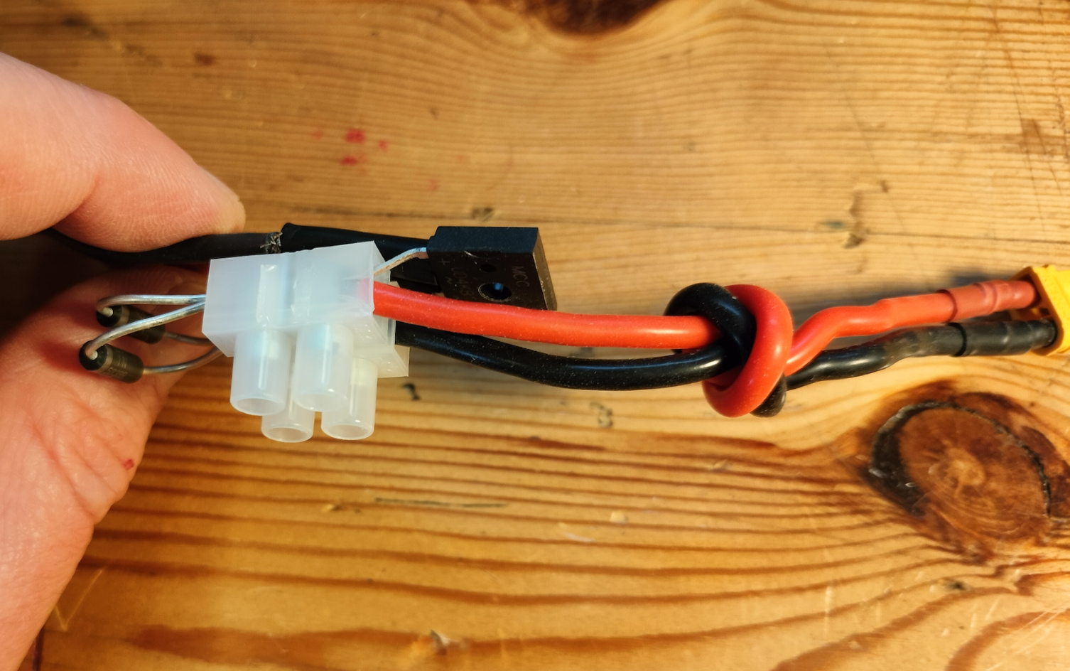
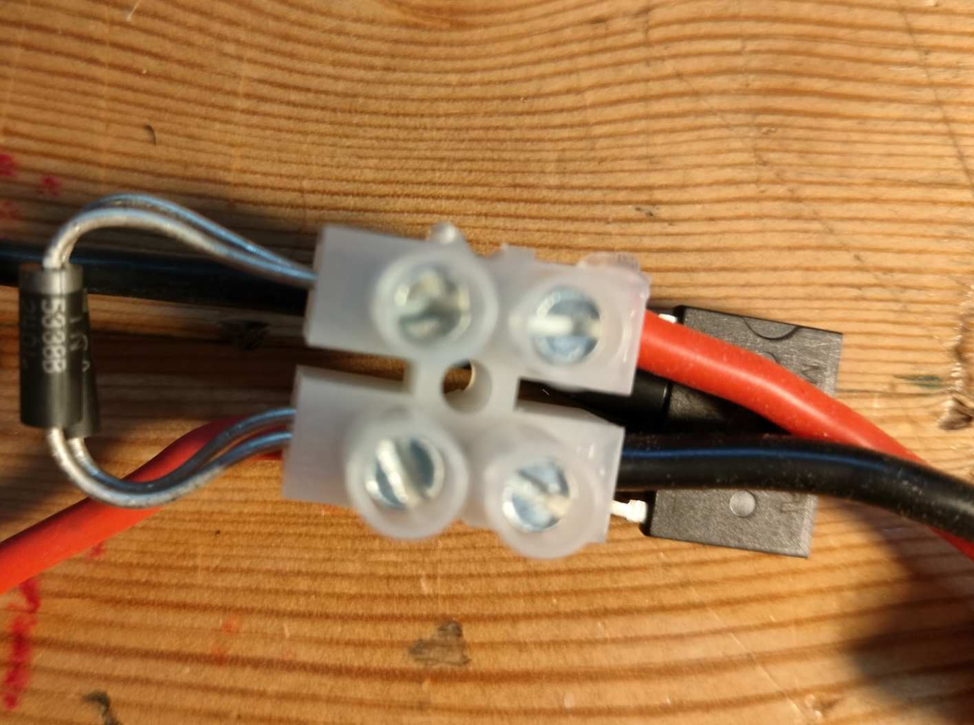
- Insert the positive leg of the rectifier output (closest to a little "+" on the rectifier) to the terminal block, along with the positive or red wire of your XT30 output wire. Put the negative leg of the rectifier in the other piece of terminal block with the black wire of the XT30 output. Tighten them up with the screws in the terminal block. Now bend the legs of the two zener diodes so they can fit into the other side of the terminal block. Make sure the silver bands are closest to the legs that go in on the side with the red or positive output wire.
- Electrically speaking everything is in place, so you can test it by plugging in a motor and seeing if it turns when you crank it. If so, you are good to go and can put the tube / cover on as shown below to protect your circuit. If not, look over the connections to see if perhaps polarity is wrong, or try it the other way.
- The XT30 output wire gets bent around a lot in the course of use, so we need to provide some strain relief so it won't eventually break. You can try to stick it through a small piece of clear tubing that's only slightly bigger than the wires, which will keep it from being bent too sharply. If it's too big to fit through, just cut a slit down one side of the clear tube, and then fit it over the output wire.
-
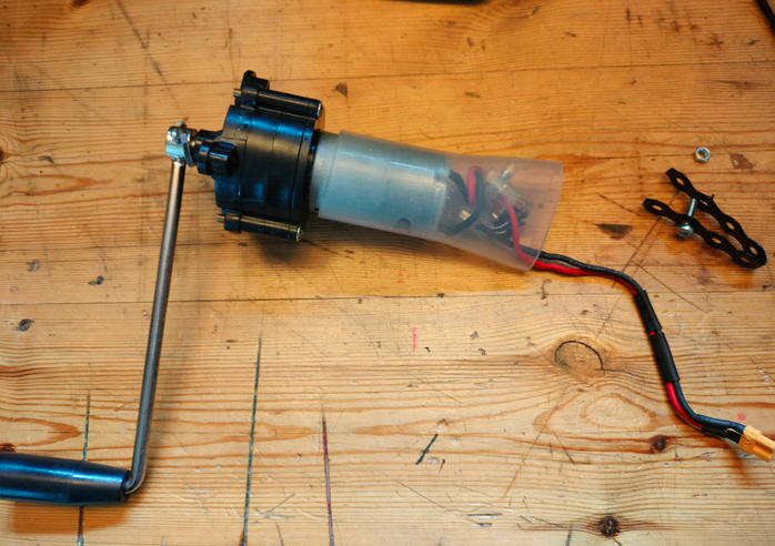
Place the large silicon pipe over the back of the generator. If it doesn't hold tightly to the generator, you may need to use a hose clamp to keep it attached.
-
Cut a piece of plumber's strap that's 7 or 8 holes long and fold it in half so that the holes align. Place it over the back of the silicon tubing so it holds it closed. Jam a sharp punch or a small phillips head screw driver through two holes to make a path for the bolt.
-
Push the bolt through the strap and the tube and place the nut and lock washer on the other end and tighten. This should form a clamp that holds tightly around the tube providing strain relief for the XT30 output cable. It needs to hold tightly so that when kids pull the output wire, the strain just pulls against the large tube, and doesn't pull against the electrical connections, which otherwise might get pulled out.
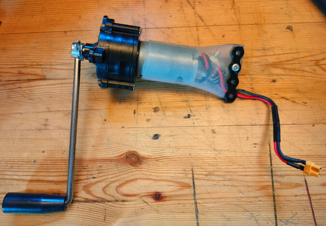
-
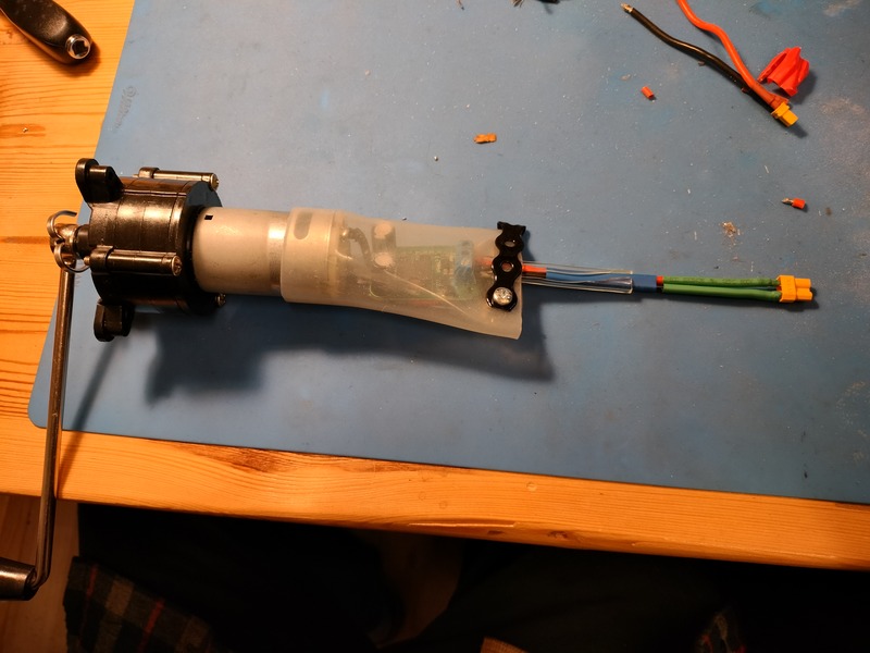
When complete the generator should look about like this (though a longer output wire has some advantages). Make sure that it provides 5 Volts of output when cranked either way.
Desired improvements
For future revisions, here are a some desired improvements.
- Right now it gets harder to crank when you crank faster, because the Zener is just eating all of the current. We're not sure if that's the best approach, or if it would be better if it got easier to crank when it wasn't generating any power. There may be some pedagogical value to matching how hard it is to crank to how much power is being generated that we are missing out on, but we'll have to watch and see.
Past revisions
Rev 3A and 3B: The 5V power conditioner
This one used a 5V step down power converter we found on Aliexpress. The first batch we got worked fine, and supplied a nice 5Volts - but it did need to be cranked pretty fast to make any power. That's because it used step down converter that wouldn't start working until the crank made 7+ volts, whereas the current revision starts giving power right away. We also ran into trouble when we got a second batch that looked more or less the same, but had short-circuit protection built in. This meant that when charging an empty power-pack, the conditioner would wrongly detect a short circuit, and stop delivering power except in small bursts. That was a pain to figure out! We opted for a cheaper, more responsive solution using Zener diodes.
3 A didn't have the rectifier, which we added for 3B so that people didn't feel confused about which way to turn.
Rev. 2a and 2b. A Little too Cheap
2a. Was a clear handheld one with a lightbulb that lit when you spun it. It strips the gears when you crank too fast, feels flimsy, and takes too long to charge a powerpack. And we had to add a diode in to keep the powerpack from back driving it like a motor. It was nice that it was clear though. You can kind of see it in action on this link to a Toot on Amos' Fediverse.
2b. Is a cheap little USB one. About 1/2 of 5 I ordered didn't work, they charge very slowly and broke very quickly. Junk, unfortunately.

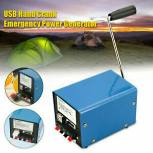
Rev. 1. The Blue Box
- Charges quickly and can be set to 5V and many other voltages, which works well but adds risk and complexity. If the kids set it to any higher voltage, it will blow up the component it is plugged into. We put duct tape over the controls and made an XT30 charge wire, and this worked fairly well. But it's much more expensive than later revisions, and also larger, heavier, and seems less robust.
- Note of risk: Using the USB output doesn't confine it to 5 volts, which means if you plug anything USB into it and set the voltage higher than 5, it will probably blow that up too. :(