Miscellaneous Elements
Wires and Connectors
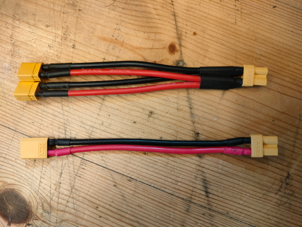
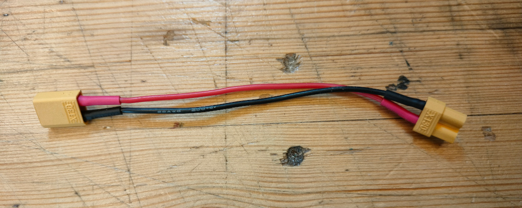
Wires and connectors allow you to connect the different electronic components of the system. All elements use XT30 connectors, which are keyed to fit only with the correct polarity. They are relatively easy for small hands to work with, at least compared to most alternatives. If the connectors are too hard to get together or pull apart, they can be lubricated with vaseline or other non-toxic lubricant.
Inputs always look like sockets (but are male), and outputs look like plugs (but are female). In workshops, we provide each builder four or five patch cables (plug on one side, socket on the other) and two Y cables. The Y cables have one output plug (female XT30) and two input sockets (male XT30), which allows builders to plug more than one power source output (i.e. two solar panels) into one input (a motor, or perhaps a solarengine and a motor.) We don't usually provide Y cables with one input and two outputs (the sort you might use to plug two motors into the output of a solarengine) because we find that splitting the output voltage that way makes the motors too weak.
Sourcing Parts
-
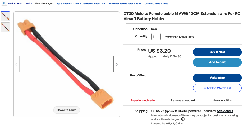
10 CM XT30 patch cables can be purchased on EBay from many different sellers. Be sure to shop around for price (especially with shipping) because it can vary dramatically from seller to seller.
-
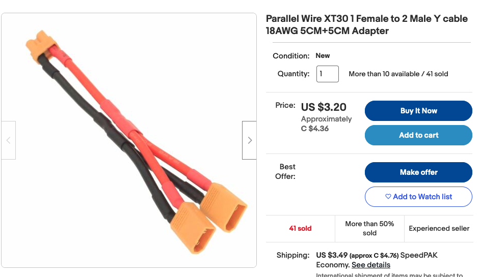
Y Cables. For input only Y cables, you'll need 1 Female (XT30 plug) to 2 Male (XT30 sockets). Here's a listing on EBay.
Desired Improvements
- We looked at a lot of connectors, but very few were robust, inexpensive, polarized, and easy to grip. XT30 has a bright yellow connector that makes the connections very visible, and is easier to grip than most. The ones we got from eBay were easy to insert and remove, unless they get sand or grit in them, in which case it helps to blow them out. But if someone finds a new connector that meets these criteria, for which inexpensive patch cables can easily be sourced, please let us know! Connectors are very important.
Past Revisions
- The 16 gauge wires can be a bit too firm and inflexible. We experimented with some 22 gauge smaller wires, which are plenty big enough to carry the small amount of current we are using. But these turned out to be too flimsy. In general silicon insulated wire seems better as the wire will usually have more "give" and flexibility to it. We're now using 18 gauge, but our 16 gauge wires aren't so bad.
Acrylic Mirrors
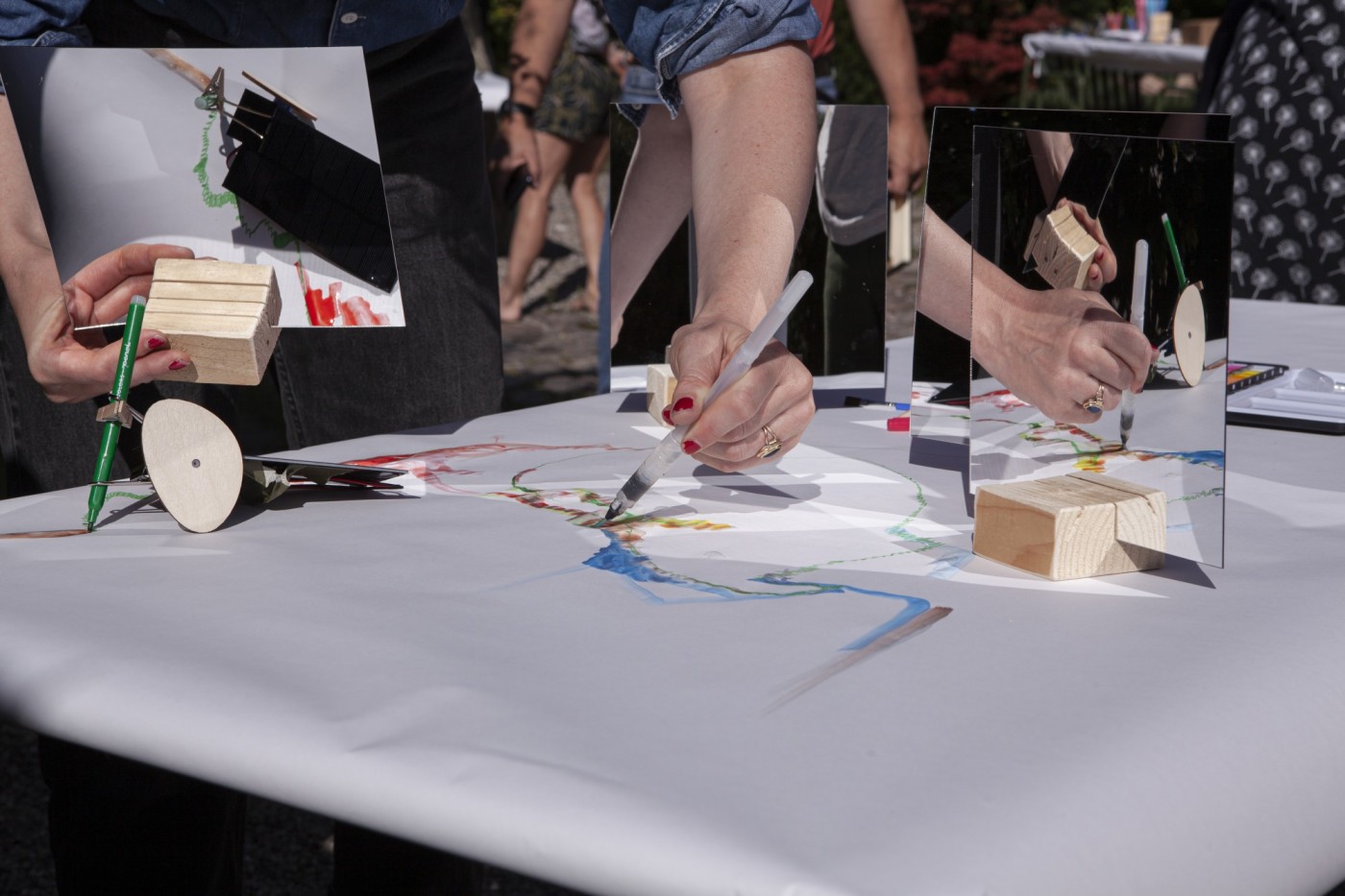
Acrylic Mirrors (usually A4 or letter size) are inexpensive and allow participants to experiment with reflecting more light onto the solar panels, which gives them noticably more power.
Desired Improvements
- Somewhat larger parabolic mirrors - say approximately 30cm - would allow for much stronger concentrations of light to be focused onto the panels. We explored this but didn't find a simple and inexpensive means of building them. But there's great play potential here.
Logo Files

Solar Panels v. 2.0 (1 watt) deprecated
These instructions are now deprecated, as the current panel is the .5 watt stackable kind. They are kept here for reference in case anybody needs to build 1 watt panels.
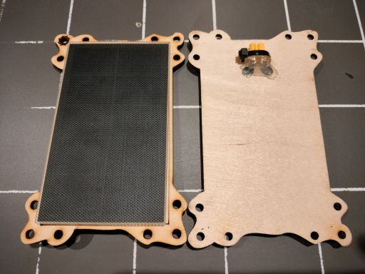
These solar panels provide approximately 1 Watt of power at 6V in full sunlight. They can be used to power motors directly, or with a solarengine in between the panel and the motor for a larger working range of light. They can also be used to charge a powerpack, but that takes a minute or so in full sun, as the powerpacks hold a lot of energy.
They can generate much less power from artifical lighting than from the sun, because most indoor lighting has a limited spectrum. From the perspective of power generation from the panels, LED's are the weakest, fluorescents have a tad more, and tungsten or halogen lights provide the most power. But even 1000 Watt Halogen lights don't provide much when the panels are > 1 meter away from them.
Parts and Tools
- 1.2 watt 6 Volt Solar panel P123 from Voltaic.
- Right Angle PCB Mount XT30 Connector (technically it is female - but it looks like a plug). We'll attach this to the panel so you can plug in and get power from it.
- 4mm plywood for lasercutting the solar panel frame.
- VHB Tape 4941, approx. 12mm wide. This is a very strong and permanent acrylic bonding double sided tape from 3M.
- Zip ties and hot glue.
- Bits of small wire to solder between legs of XT30 and the pads of the solar panel.
Tools Needed:
- Soldering iron and solder
- Wire stripper
- Hot glue gun
Assembly Instructions:
-
Lasercut the panel frames from the plywood, using the sol-panel-frame .svg file located in the Gitlab repository.
-
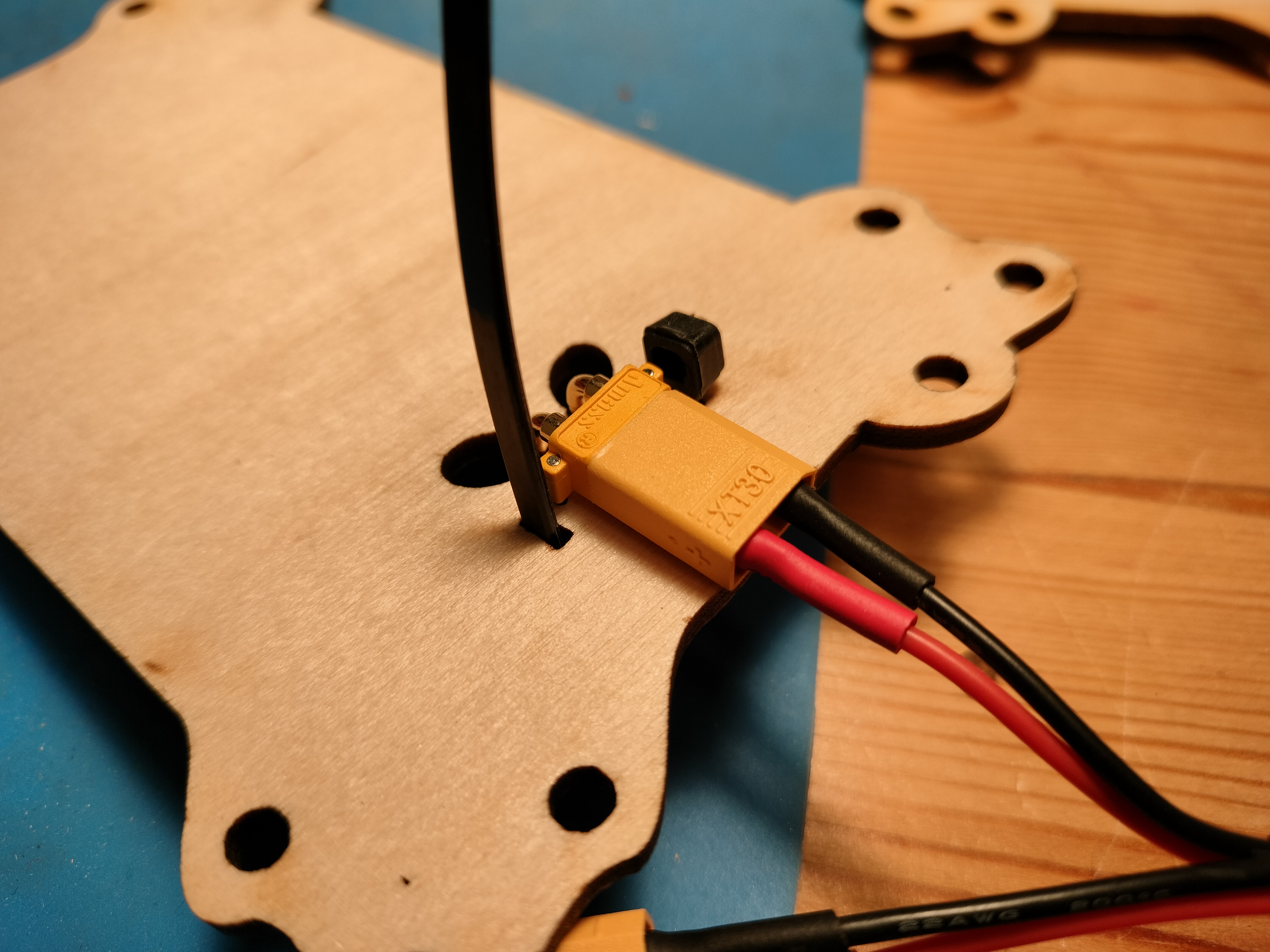
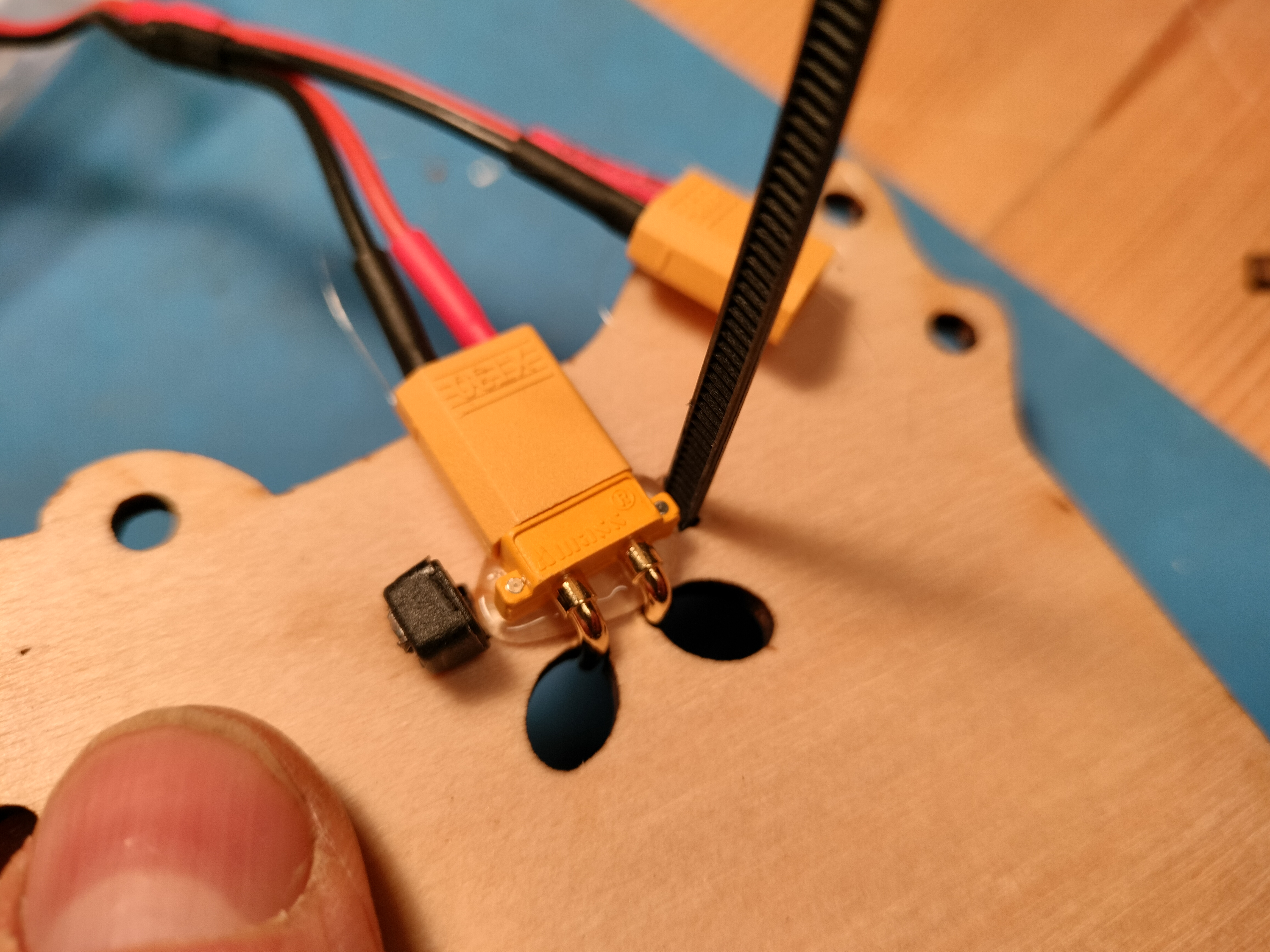
Now take your XT30 connector and connect it to one of the XT30 patch cables, to protect the connector from getting glue on it. The connector has little pins on the bottom in addition to the larger electrical "feet" that fit into the back of the solar panel frame. Place a zip tie through the frame as shown.
-
Remove the connector and spread a bead of hot glue under where the connector fits, and then stick it back in place while the glue is still hot. This forms a bed of glue for the connector to fit onto.
-
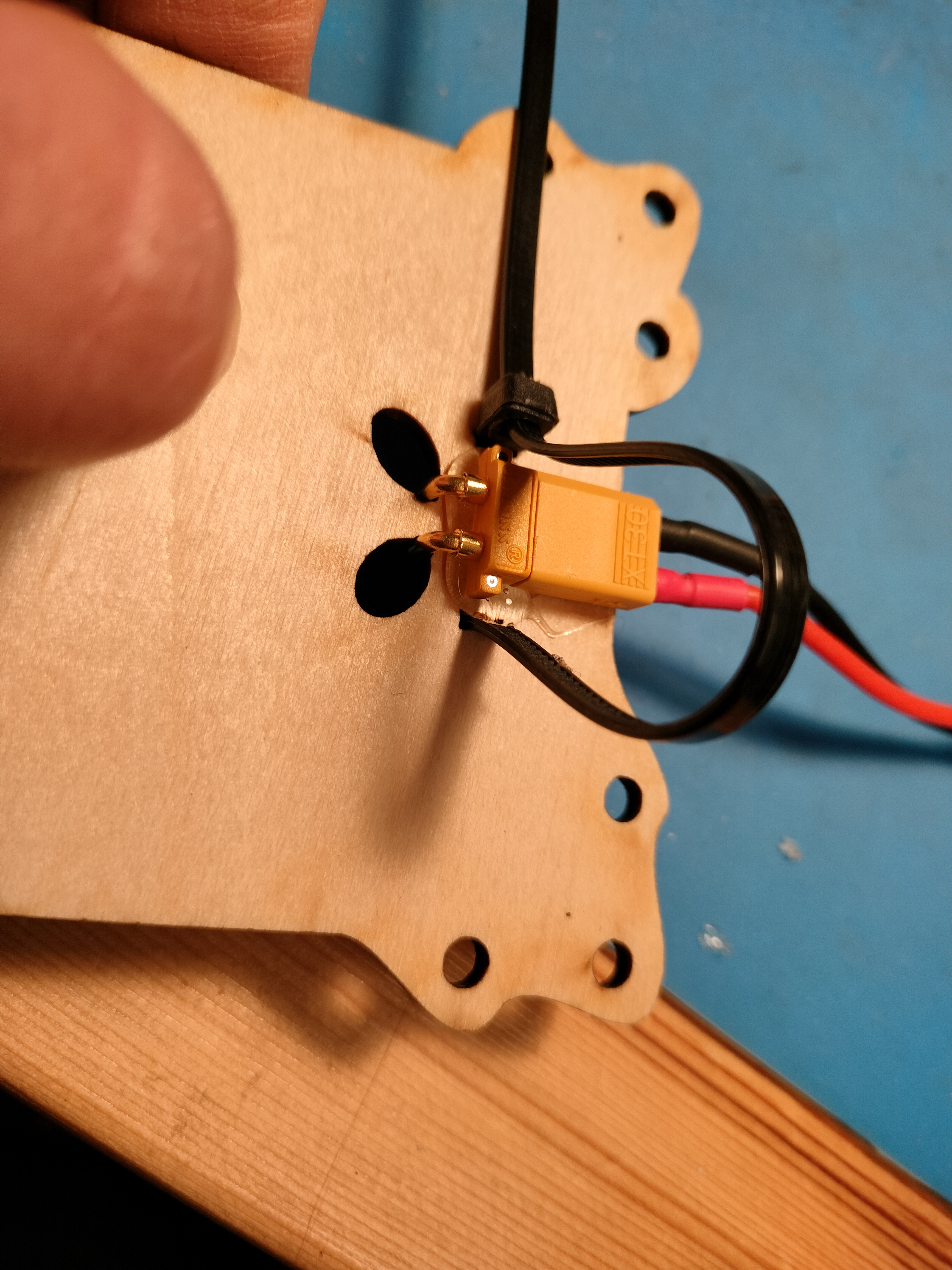
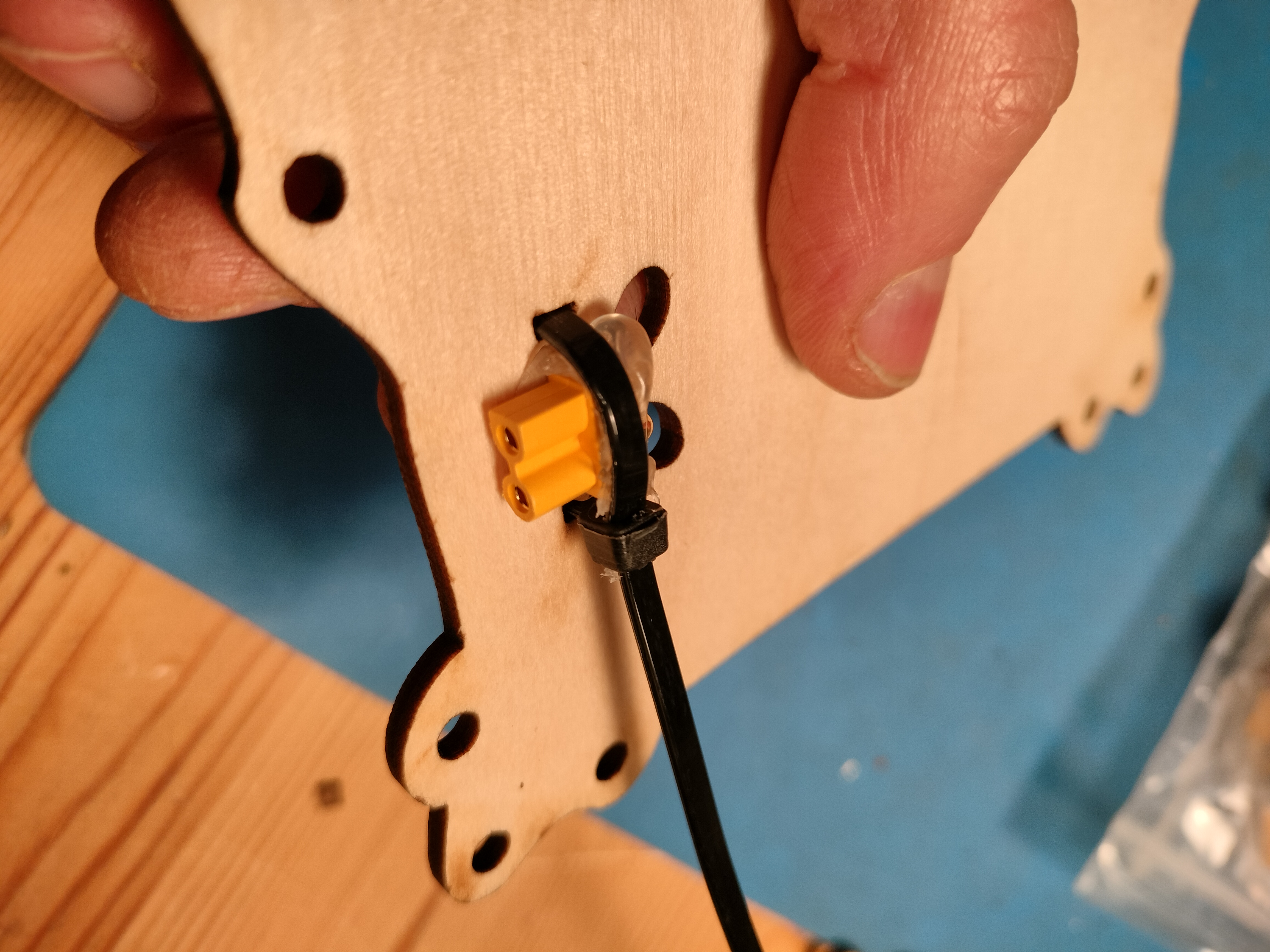
Thread the zip tie end through the lock, but don't tighten it yet. Now spread a bead of hot glue over the top of the XT30 connector, and then pull the zip tie until it is very tight, holding the connector tightly onto the solar panel frame. The hot glue should form a bed that keeps things in place. Once the hot glue has cooled you can remove the Xt30 patch cable, and trip the end off the zip tie.
-
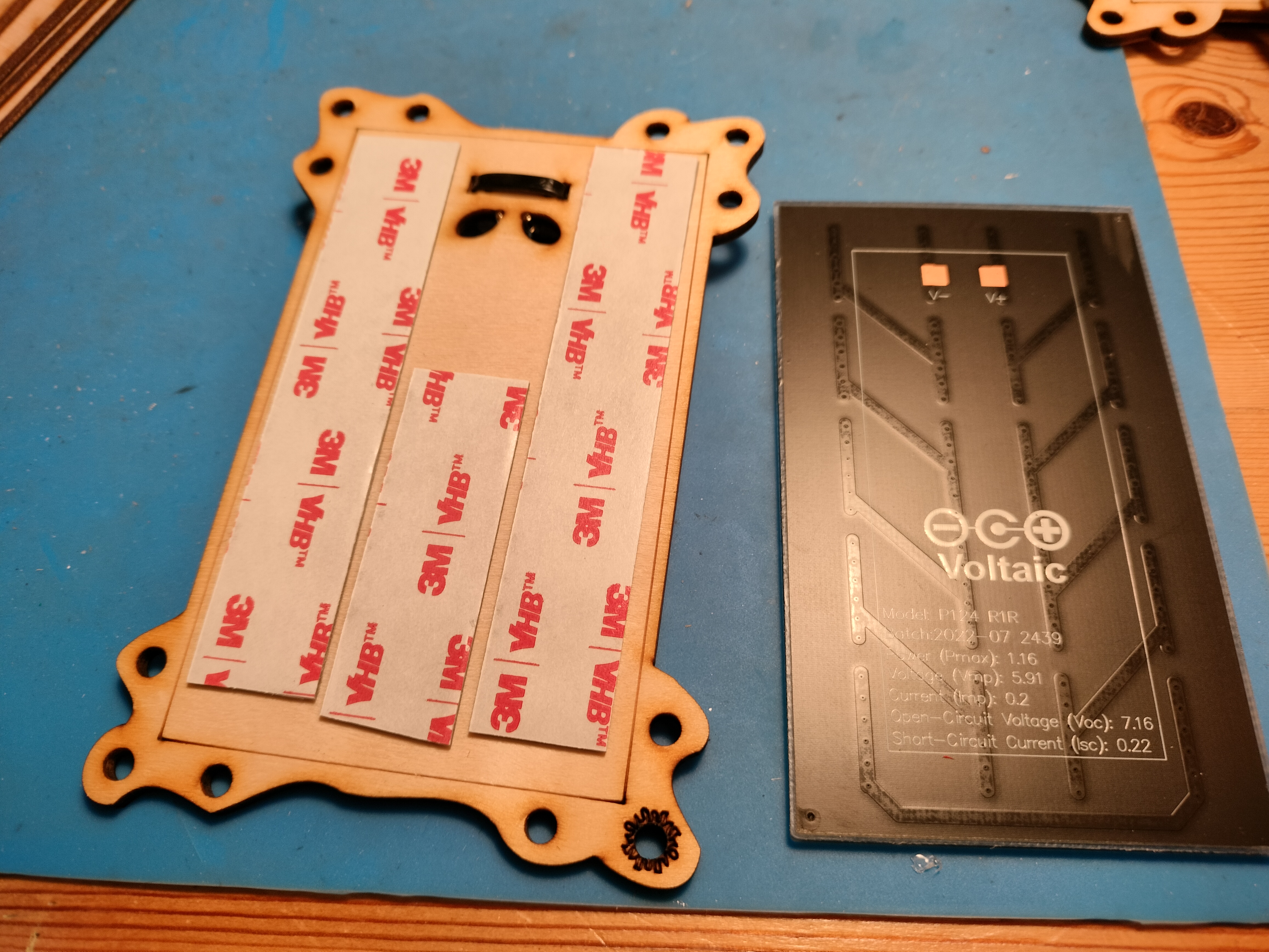
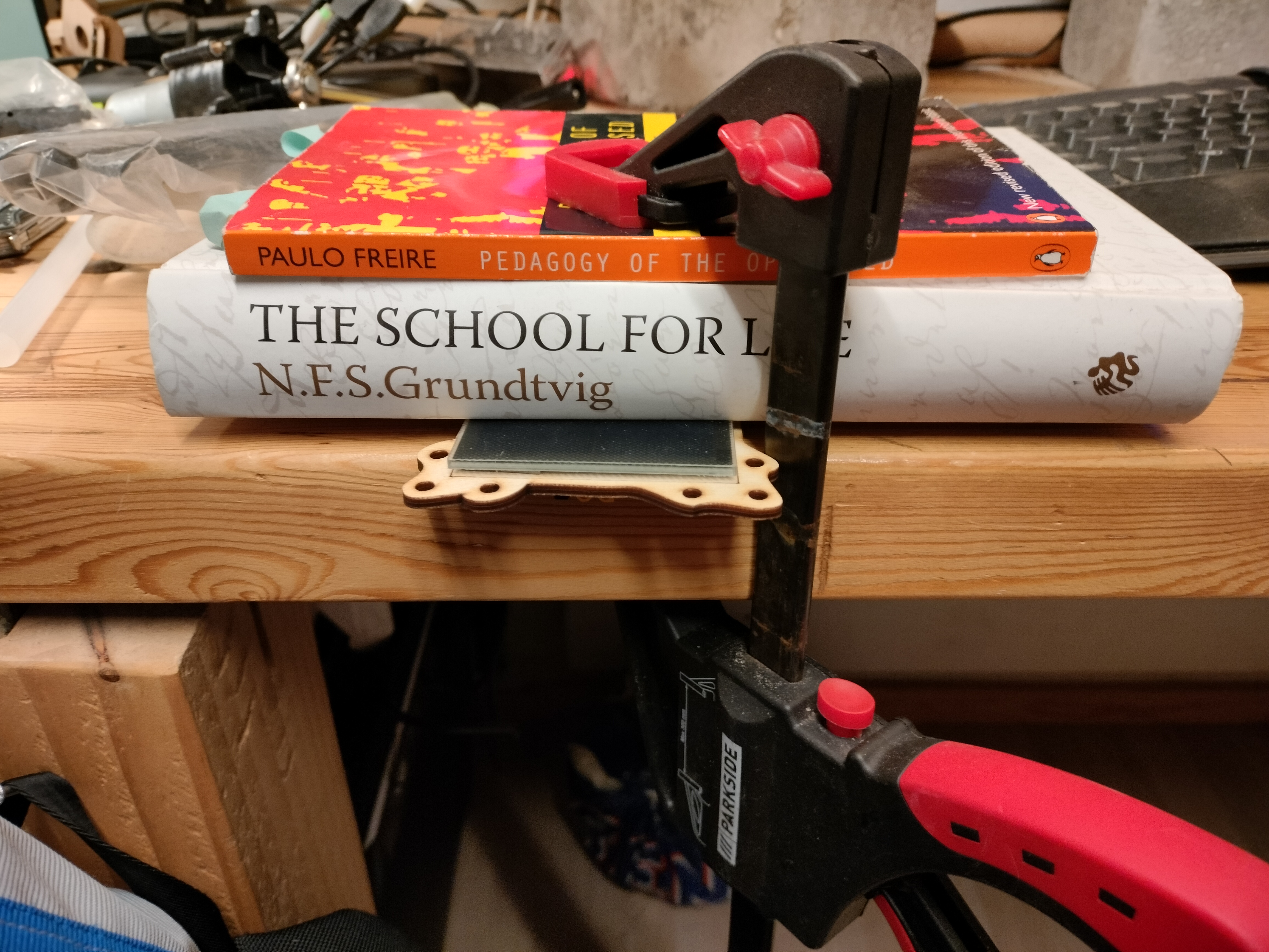
Flip the panel frame over and apply VHB tape to the area within the outlined frame. Remove the tape backing, and place the solar panel against the frame with the solder pads on the same side as the legs of the XT30 connector. It should line up with the outline of the panel etched onto the front of the panel frame. Clamp or place weights on the panel and frame for at least a few minutes so the VHB has time to make a good bond.
-
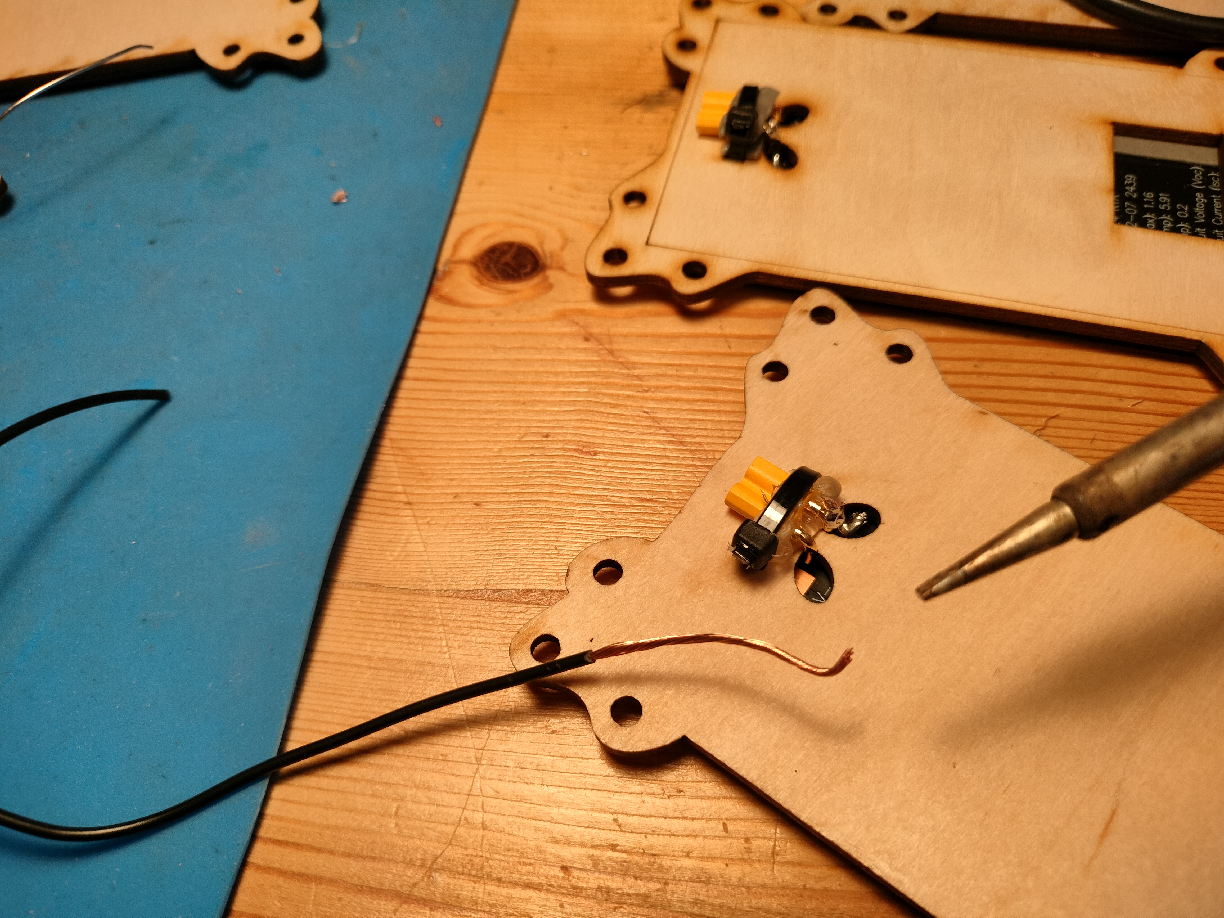
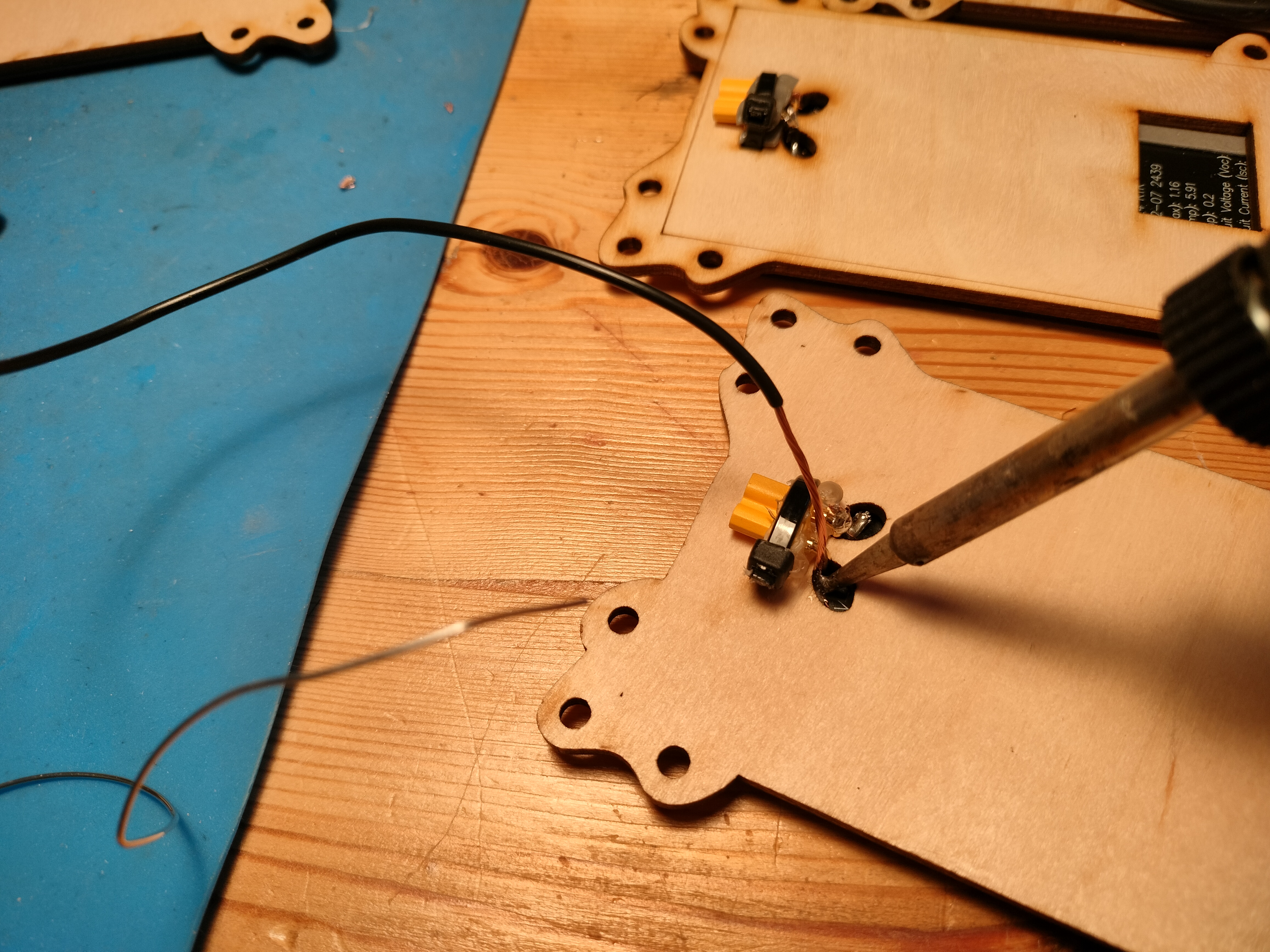
You might think you could solder the legs of the XT30 directly to the solar panel pads. That might work, but we're worried that solder is a bit too brittle, and will crack when the panel gets flexed by kids playing with it. So the recommended way is to take a length of any old wire and bend the end so that you can press it against the solder pad of the solar panel and solder it on. Next hold the wire close to the outside of the leg of the XT30, and solder it on to the leg. That should make it able to handle flexing a bit better. Do the same for the other leg of the XT30.
-
Once the connector is soldered on, test it by plugging it into a volt meter and holding the panel to the light, or by plugging it into a PwtS motor and giving it full sun. Once you are sure the soldered connections are working as they should, cover them with hot glue. Your panel should be all set!
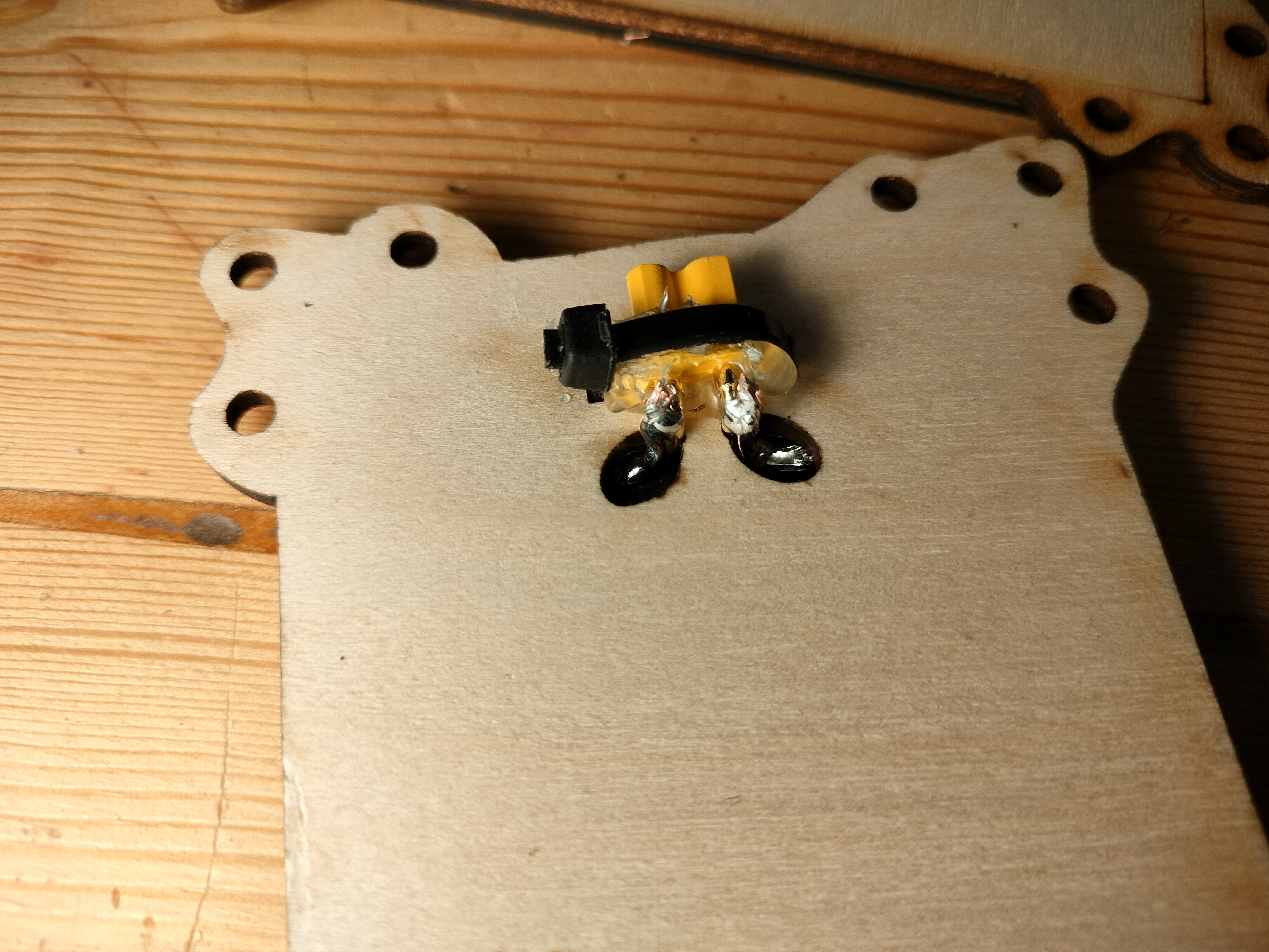
Thanks to Jørgen Tietze of Vejle Library for the (great!) idea of using a zip tie to anchor the connector.
Desired Improvements
- Round panels would fit the aesthetic better.
- There are solar panels that work better with indoor light frequencies, but we haven't found any that are inexpensive. It would be nice if we could find some that can be used with LED work lights indoors on rainy days. This would give us a lot more flexibility when planning workshops.
- Should we try integrating the solarengine circuitry into the solar panels, thereby simplifying the construction kit by removing a major component? It would make things simpler in some ways, but more complex to build in others. Would it further "black box" the solarengine and the panen in a way that is potentially confusing for kids?
Past Revisions
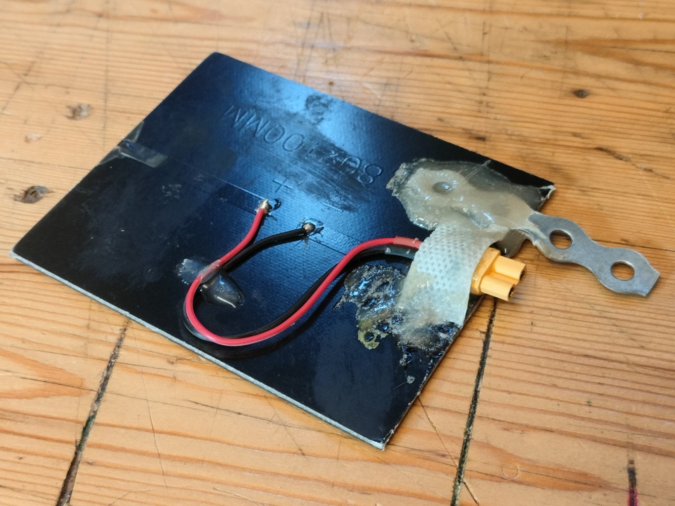
- The first revision just had the outputs soldered to an XT30 connector, slathered in epoxy. ( These had Left and Right versions because the plumber's strap was either left or right of the connector, which created a problem if you need one type but couldn't immediately find it. This is why current revisions have the connector at center.
